Systems and methods for dynamically reconfiguring automatic test equipment

a technology of automatic test equipment and dynamic reconfiguration, applied in the field of systems and, can solve the problems of inability to test that technology, inability to apply speed and/or collect responses, signal applied or received between the instruments and the uut further degraded and interfered by the interface between

Active Publication Date: 2018-07-19
A T E SOLUTIONS
View PDF8 Cites 11 Cited by
  • Summary
  • Abstract
  • Description
  • Claims
  • Application Information

AI Technical Summary

Benefits of technology

[0038]The instrument of the present invention is reprogrammable and tunable to adapt to the requirements of new UUTs. For instance, if the unit under test is a USB 3.1 device but requires higher drive, then only the portion of the instrument that needs to change to support higher drive will change. The instrument is also reprogrammable to be able to adapt to the requirements of the UUT. For instance if the UUT has a USB 3.1 bus and a HDMI bus, the instrument can first configure itself to test the USB and then reconfigure itself to test the HDMI, or the other way around. The instrument manages the speed discrepancy between the UUT and the ATE upon which it is hosted, ensuring that the test can be run at full speed and the results returned at the speed capabilities of the host ATE. The instrument can test both analog and digital characteristics of the unit under test.
[0039]One advantage that derives from a synthetic instrument of the present invention is that several copies of the same instrument can be made to test in parallel. For example, an ATE may have a limited number of digital volt meters (“DVM”), and in order to test eight outputs it would have to test each output in sequence. However, using a synthetic instrument of the present invention one can configure eight DVMs (limited only by the resources within the FPGA) so that all eight outputs can be tested simultaneously.

Problems solved by technology

The ATE may utilize the fastest electronics technology available when the ATE was designed, but as faster technology emerges, the ATE is unable to test that technology.
The first is that the instrumentation cannot apply speeds and / or collect responses at the speed required to test the high speed UUT.
The second is that the signals applied or received between the instruments and the UUT are further degraded and interfered with by the interface between them.
In the best of circumstances this interface includes cabling and switching, which already distorts the signal sufficiently to make accurate signal transmission impossible.

Method used


Image

  • Systems and methods for dynamically reconfiguring automatic test equipment
  • Systems and methods for dynamically reconfiguring automatic test equipment
  • Systems and methods for dynamically reconfiguring automatic test equipment

Examples


Embodiment Construction

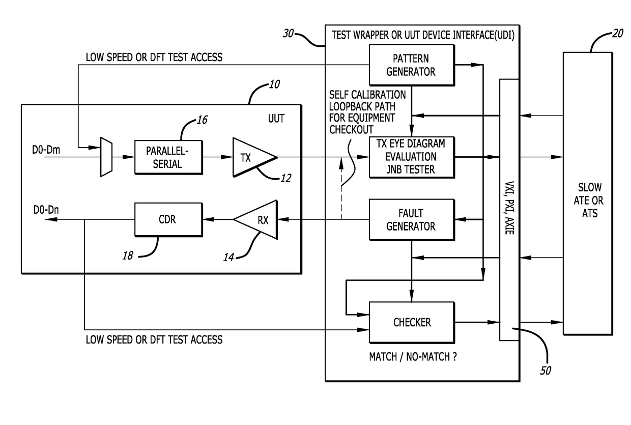
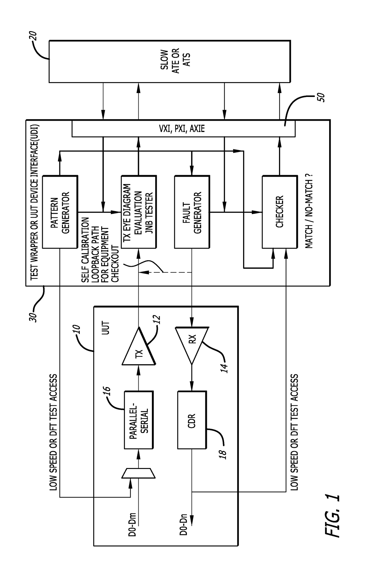
[0047]The present invention is a furtherance of the manner in which integrated chip manufacturers have utilized design for testability in overcoming the obstacles presented by high speed I / Os. The wrappers used in system-on-chip applications are not expected to be present in the certain LRUs, but with the present invention a Test Wrapper is placed outside of the LRU using an interface board between the UUT and the ATE. This mechanism is also referred to as a UUT Device Interface (UDI). The present invention uses an intelligent wrapper that contains all the test resources necessary to apply test patterns, make JNB measurements, inject faults, provide physical layer and protocol layer test services, and collect and analyze responses. Because of high speed requirements, the present invention leads to direct and close proximity access with the UUT's Tx / Rx pair as multiplexing or even moderate distance transmissions can compromise signal integrity.

[0048]A schematic of the test architectu...


PUM


Abstract

A dynamically reconfigurable interface for an automatic test equipment is disclosed where one or more synthetic instruments transmit the high speed signals as well as receive the high speed signals from a device under test so that testing can be performed at speeds higher than the ATE was originally designed to accommodate. Synthetic instruments are implemented on a field programmable gate array (FPGA) that operate at higher speeds than COTS instruments and can reach the frequencies that high speed I/O buses use. SIs can be created by configuring the FPGA, with different configurations creating different SIs. A single FPGA can house a number of SIs.

Description

CROSS-REFERENCES TO RELATED APPLICATIONS[0001]This application claims priority from U.S. Provisional Patent Application No. 62 / 446,135, filed Jan. 13, 2017, the content of which is incorporated by reference in its entirety.BACKGROUND[0002]High speed testing of integrated circuit bus structures is an emerging technology. The rapid doubling of digital signal speeds, now reaching from 56 Gbps (giga bits per second, where giga is 1,000,000,000) to 112 Gbps in state-of-the-art circuits, requires new measurement solutions. Additionally, it is not sufficient in a test to simply apply a traditional test signal and evaluate a response within the given specifications. By the very nature of tests and the need to detect and diagnose faults and failures, well controlled out of specification signals need to be evaluated. For example, it is preferable not only to measure noise that is on a signal to determine whether it is within tolerable limits, but to also conduct a comprehensive test to genera...

Claims


Application Information

Patent Timeline
Patent Type & Authority Applications(United States)
IPC IPC(8): H04L12/26G06F11/22
CPCH04L43/087H04L43/0847H04L43/14H04L43/50G06F11/221G06F11/263G01R31/31905G01R31/31908
Inventor UNGAR, LOUIS YEHUDAMAK, TAK MINGJACOBSON, NEIL GLENN
Owner A T E SOLUTIONS
Why Eureka
Try Eureka