Bladed disc and method of manufacturing the same

Active Publication Date: 2018-07-26
ROLLS ROYCE PLC
View PDF8 Cites 6 Cited by
  • Summary
  • Abstract
  • Description
  • Claims
  • Application Information

AI Technical Summary

Benefits of technology

[0014]For blades, that have a relatively low volume, the residual stress imparted by friction welding may be difficult to relieve by heat treatment particularly as the alloys used have high

Problems solved by technology

As a result, non-mechanical methods of joining the blades have been proposed, wherein the bladed discs are machined from a single forged piece.
However, such methods suffer from manufacturing challenges due to less efficient utilization of expensive materials and expensive forging machinery.
Due to technical challenges associated with a high temperature environment, the bladed discs are required to be fabricated with dissimilar materials.
However, there are technical challenges in joining two dissimilar materials.
For example, joining of the dissimilar materials, i.e. a blade and disc alloys having different crystal structures, differences in thermal proc

Method used


Image

  • Bladed disc and method of manufacturing the same
  • Bladed disc and method of manufacturing the same
  • Bladed disc and method of manufacturing the same

Examples


Embodiment Construction

[0038]In the following description, the wording ‘contact’, ‘abut’, ‘connect’ and ‘couple’, and their derivatives, mean operationally contacting, abutting, connecting and coupling. It should be appreciated that any number of intervening components may exist, including no intervening components.

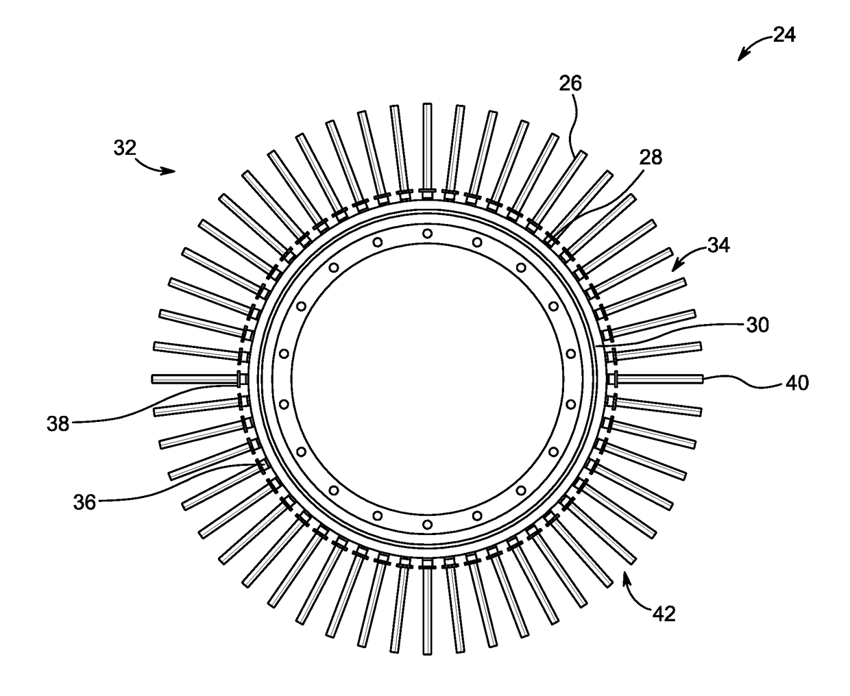
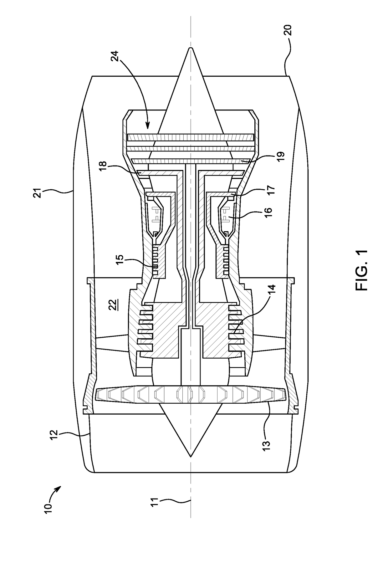
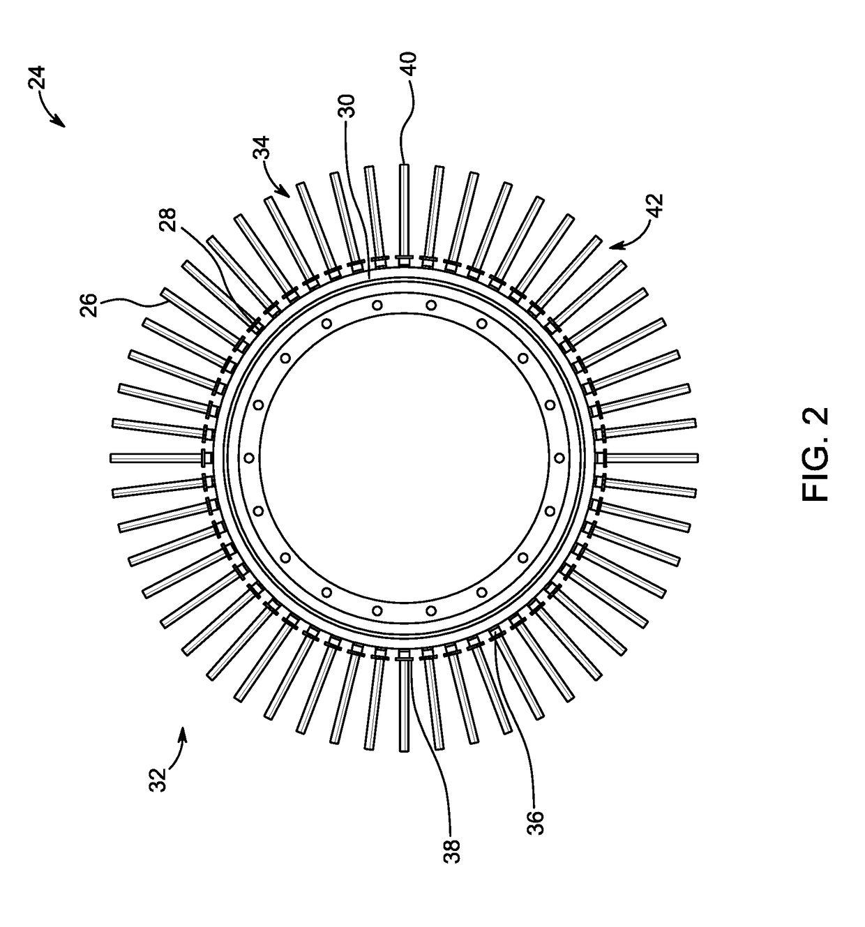
[0039]With reference to FIG. 1, a gas turbine engine is generally indicated at 10, having a principal and rotational axis 11. The engine 10 comprises, in axial flow series, an air intake 12, a propulsive fan 13, an intermediate pressure compressor 14, a high-pressure compressor 15, a combustion equipment 16, a high-pressure turbine 17, an intermediate pressure turbine 18, a low-pressure turbine 19 and an exhaust nozzle 20. A nacelle 21 generally surrounds the engine 10 and defines both the air intake 12 and the exhaust nozzle 20.

[0040]The gas turbine engine 10 works in the conventional manner so that air entering the air intake 12 is accelerated by the propulsive fan 13 to produce two air flows...


PUM

PropertyMeasurementUnit
Material propertiesaaaaaaaaaa

Abstract

A method (56) for fabricating an integral assembly (24) is disclosed. The method comprises providing (56) a first workpiece (26) having a first surface (46) and a second workpiece (28) having a second surface (50), performing a first bonding process between the first surface (46) of the first workpiece (26) and the second surface (50) of the second workpiece (28) to form a sub-assembly workpiece (48), and performing a second bonding process between a third surface (52) of the sub-assembly workpiece (48) and a fourth surface (54) of a third workpiece (30) to form the integral assembly (24). The material properties of the first workpiece (26) are different from material properties of the third workpiece (30).

Description

CROSS-REFERENCE TO RELATED APPLICATIONS[0001]This disclosure claims the benefit of GB Patent Application No. GB 1701236.0, filed on 25 Jan. 2017, which is hereby incorporated herein in its entirety.FIELD OF THE INVENTION[0002]The present disclosure relates to a bladed disc and a method of manufacturing the same.BACKGROUND[0003]Gas turbine engines are employed in a variety of applications, such as aircraft, and marine vessels, among others. The gas turbine engines generate a thrust from a fluid flow by first compressing an intake air within a compression unit. The compression unit utilizes a series of bladed discs or bladed rings for compressing the intake air. The compression unit supplies the compressed air to be mixed with a fuel mixture for combustion in a combustion unit. The resulting hot, high pressure gaseous mixture is expanded through a turbine portion to extract energy which drives the compressors and a propulsor such as a fan or propeller. Energy may also be extracted in ...

Claims


Application Information

Patent Timeline
IPC IPC(8): F01D5/30F01D5/12F01D5/02
CPCF01D5/3061F01D5/12F01D5/02F05D2220/32F05D2230/239F05D2230/236F05D2300/175F01D5/025F01D5/28B23K20/02B23P15/04B23K20/122F01D5/34Y02T50/60
Inventor BOSWELL, JOHN H.WALPOLE, ANDREW R.
Owner ROLLS ROYCE PLC
Why Eureka
Try Eureka