
Heating plate

a technology of heating plate and plate body, applied in the field of electric heating, can solve the problems of affecting the service life of the product, and the time of manufacture is longer, so as to shorten the production cycle time, reduce the number of workers, and simplify the production process

Inactive Publication Date: 2018-07-26
ZHONGSHAN SONGJING ELEC CO LTD
View PDF3 Cites 0 Cited by
  • Summary
  • Abstract
  • Description
  • Claims
  • Application Information

AI Technical Summary

Benefits of technology

The present invention provides a heating plate with high efficiency and reliability. The heating plate has a cast iron blank, a heat generating tube, and a heat insulating powder layer, providing double protection for the heat generating element. The production process is simplified, resulting in a shorter production cycle time, reduced labor costs, and lower production consumption and labor costs. The heating efficiency is faster than traditional heating plates and is maintained for a longer period of time. The surface coating with nano-inorganic ceramic further enhances the performance of the heating plate. The heating element applies an iron chrome aluminum alloy resistance wire which has good heat generating performance and low cost. The cast iron blank is made of gray cast iron with good heat transfer performance due to its wave and thread shape surface layer. The inner plate has an insulation layer to keep warm and reduce heat loss, resulting in better energy efficiency of the product.

Problems solved by technology

Result from that the heating tube will be off or broken after many times of power-on and power-off, which will affect its service life.
However, the structure and the process of manufacture is complicated, the time of manufacture is longer, the energy consumption is higher, the moisture-exhausting temperature is higher, and manufacturing and labor costs are higher.
And in the condition of long-term storage, insulation powder will easily absorpt moisture, which make the product fail to pass the pressure test.

Method used


Image

  • Heating plate
  • Heating plate

Examples


Embodiment Construction

[0015]In order to better explain the objects, technical solutions and advantages of the present invention, the invention will be described in further details below with reference to the drawings.

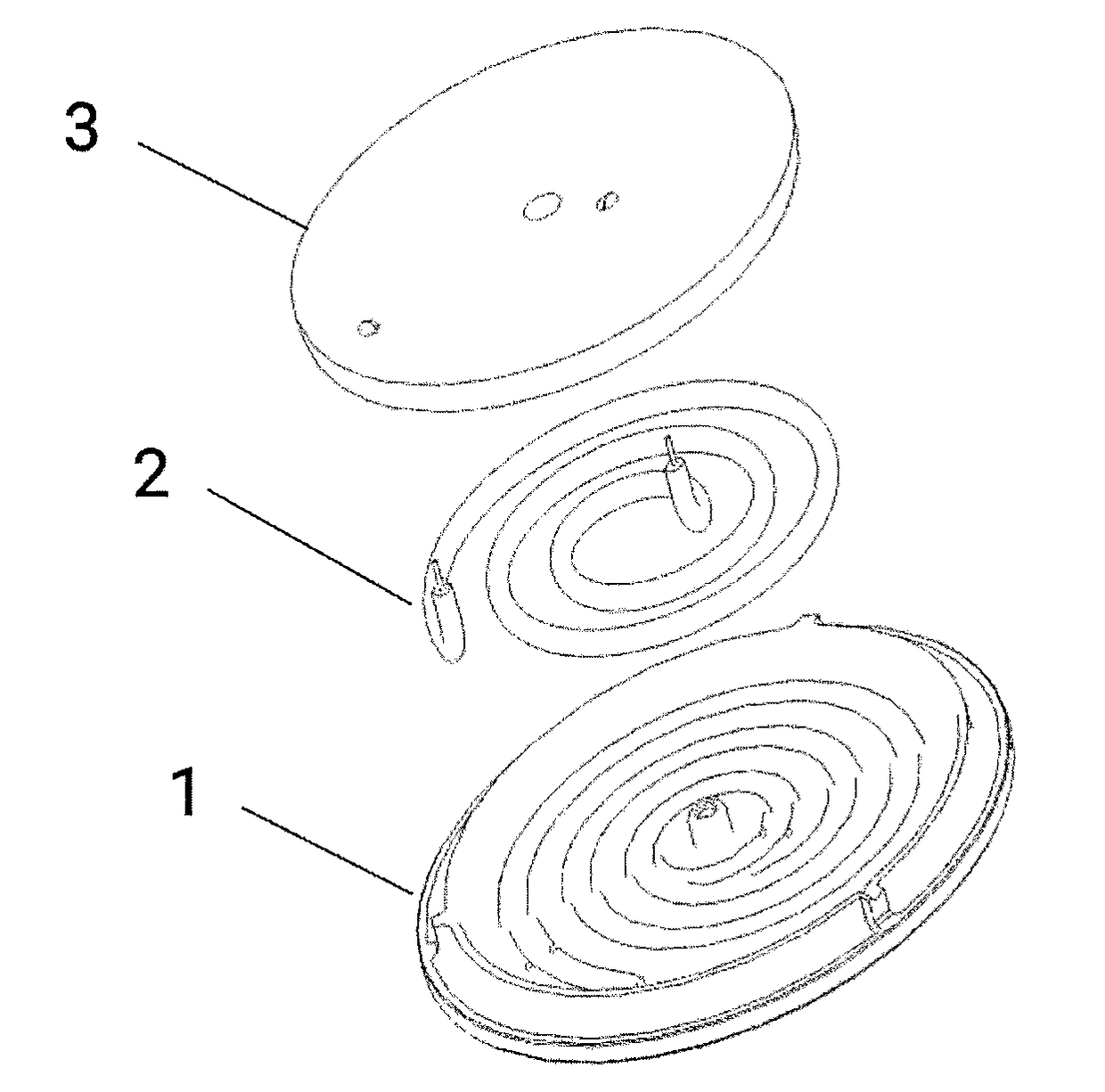
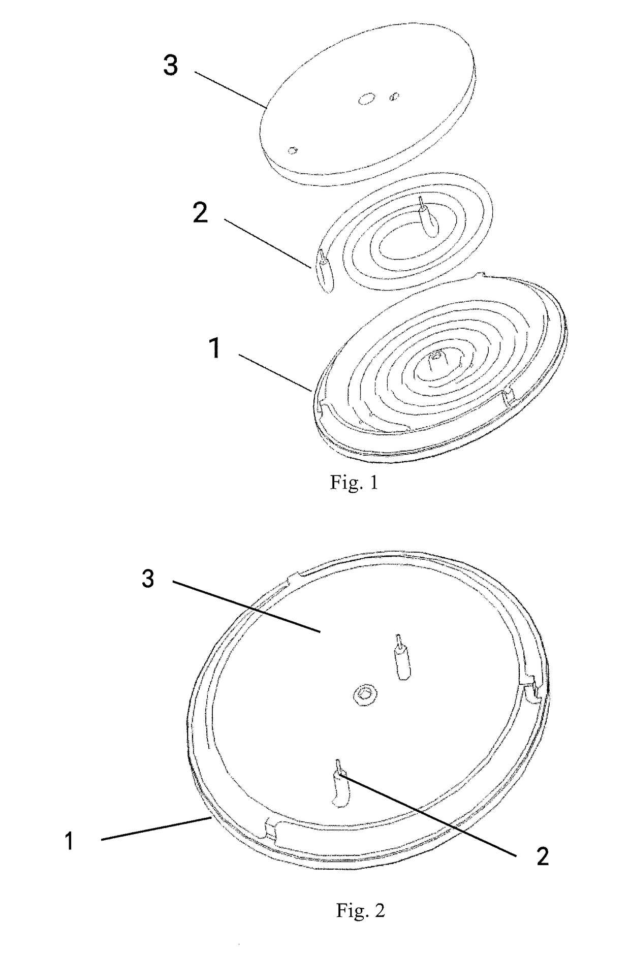
[0016]The heating plate comprises a cast iron plate blank 1, a heat tube 2 and a heat insulating powder layer 3. The upper surface of the cast iron plate is provided with a recess for placing a heating tube, which is round spiral recess based on the center of the cast iron plate. The upper surface of the cast iron plate is coated with a coating layer with spiral heating tube. The spiral heating tube is engaged in the spiral recess. And the both sides of the heat tube are respectively provided with a lead post which is perpedicular to the horizen plate. The heat insulating powder layer is fixed with two holes for leading pin of the heating tube. And the leading pin is arranged to pass through the lead pin hole, and one of the pin-posts is arranged near the middle of the cast iron plate. And t...


PUM

PropertyMeasurementUnit
thicknessaaaaaaaaaa
thicknessaaaaaaaaaa
depthaaaaaaaaaa

Abstract

An embodiment of the present invention discloses a heating plate comprising a cast iron blank, a heat generating tube and a heat insulating powder layer. Wherein the upper surface of the cast iron blank is provided with a recess for placing a heat generating tube. Thereof a heat-generating tube is pressing-fitted into the recess and is fitted with the recess, and both ends of the heat-generating tube are respectively provided with a leading pin perpendicular to the horizontal plane. And the upper surface of the heat-insulating powder layer where is provided two pin holes respectively connected with the heat generating tube leading pins, and the leading pins pass through the lead pin holes. And it is an object of the present invention to provide a heating plate with high efficiency and high reliability.

Description

FIELD OF THE INVENTION[0001]The present invention relates to the field of electric heating, and more particularly to a kind of heating plate.BACKGROUND OF THE INVENTION[0002]Heating plates in the market using the current technology are electric heating furnace, electric tea stove, electric cooking pot and the like. The traditional heating plates are generally divided into two types: one is a pressing-tube heating plate and the other is a laiding-wire heating plate. Pressing-tube heating plate is made of heating tubes and metal shell, and most of the shell are made of aluminum alloy or cast iron. In the case of pressing-tube heating plate, the heating tubes are directly pressed and fixed into the heating plate. When it is under working situation, the internal temperature is high. Result from that the heating tube will be off or broken after many times of power-on and power-off, which will affect its service life. The structure of another kind of laiding-wire heating plate is that the...

Claims


Application Information

Patent Timeline
Patent Type & Authority Applications(United States)
IPC IPC(8): H05B3/68H05B3/02H05B3/32
CPCH05B3/686H05B3/32H05B3/026H05B3/0014
Inventor OU, SONGSHENG
Owner ZHONGSHAN SONGJING ELEC CO LTD
Learn More