Electronic switchbox

a switchbox and electronic technology, applied in the field of electronic switchboxes, to achieve the effect of high impedance state and high impedance sta

Active Publication Date: 2018-08-09
ST JUDE MEDICAL CARDILOGY DIV INC
View PDF0 Cites 15 Cited by
  • Summary
  • Abstract
  • Description
  • Claims
  • Application Information

AI Technical Summary

Benefits of technology

[0007]Embodiments of the present disclosure are directed to electronic switchboxes that include impulse detection circuitry and a switch matrix with one or more switches. The impulse detection circuitry detects a pulse emitted from a signal generator, and the switch matrix operates in one of two modes. In the first mode, the pulse is electrically isolated from an electrocardiograph monitor and a plurality of catheter electrodes. In response to an activation signal from the impulse detection circuitry indicative of the pulse, the switch matrix operates in a second mode. In the second mode, the pulse is electrically coupled to at least one of the catheter electrodes, and a high impedance state protects the electrocardiograph monitor from the cardioversion pulse. In more specific / detailed embodiments, the electronic switchbox further includes charge collector circuitry electrically coupled between driver circuitry and the impulse detection circuitry. The charge collector circuitry stores energy from the cardioversion pulse and powers the driver circuitry during the pulse.
[0008]Various embodiments of the present disclosure are directed to a cardiovascular catheter system. The cardiovascular catheter system including a signal generator, an electrocardiograph monitor, a cardiac catheter, and an electronic switchbox including impulse detection circuitry and a switch matrix. The signal generator generates an electrical pulse for cardioverting or ablating tissue. The electrocardiograph monitor receives and monitors electrocardiograph signals indicative of the electrical activity of a heart. The cardiac catheter includes a plurality of electrodes along a length of a distal portion, the electrodes electrically coupled to tissue, and cardioverts or ablates the tissue in response to the electrical pulse. The impulse detection circuitry is electrically coupled to the signal generator, and detects the electrical pulse emitted from the signal generator. The switch matrix includes one or more switches, an input port, and an output port. The switch matrix is electrically coupled to the impulse detection circuitry and the signal generator at the input port, and the plurality of electrodes and the electrocardiograph monitor at the output port. The switch matrix operates in first and second modes. In the first mode, the electrical pulse is isolated from the electrocardiograph monitor and the catheter electrodes. In the second mode, in response to an activation signal from the impulse detection circuitry indicative of the electrical pulse, the electrical pulse is communicated to at least one of the catheter electrodes, and a high impedance state protects the electrocardiograph monitor from the electrical pulse. In more detailed embodiments, the electronic switch box further includes driver circuitry. The driver circuitry changes the switch matrix between the first and second modes in response to a trigger signal from the impulse detection circuitry. In such an embodiment, the impulse detection circuitry uses the energy from the electrical pulse to deliver the trigger signal to the driver circuitry.
[0009]Yet other embodiments of the present disclosure are directed toward methods of operating an electronic switch box. The method includes operating in first and second modes. In the absence of an electrical pulse, the switchbox operates in the first mode, whereby an input port of the switch box is isolated from an electrocardiograph monitor and a plurality of catheter electrodes are electrically coupled to an output port of the switch box. The switchbox operates in the second mode, in response to the electrical pulse. In the second mode, the input port that receives the electrical pulse is electrically coupled to at least one of the catheter electrodes, and the electrocardiograph monitor via the output port of the switch box. The electrocardiograph monitor is protected from the electrical pulse by a high impedance between the output port of the switch box and the electrocardiograph monitor. In more specific implementations, electrocardiograph signals from the catheter electrodes are communicatively coupled to the electrocardiograph monitor during both the first and second modes.

Problems solved by technology

However, such manual electronic switchboxes prevent the clinician from receiving ECG signals immediately following a cardioversion or electroporation therapy, as the clinician is unable to manually switch the electronic switchbox in such a short period of time.

Method used


Image

  • Electronic switchbox
  • Electronic switchbox
  • Electronic switchbox

Examples


Embodiment Construction

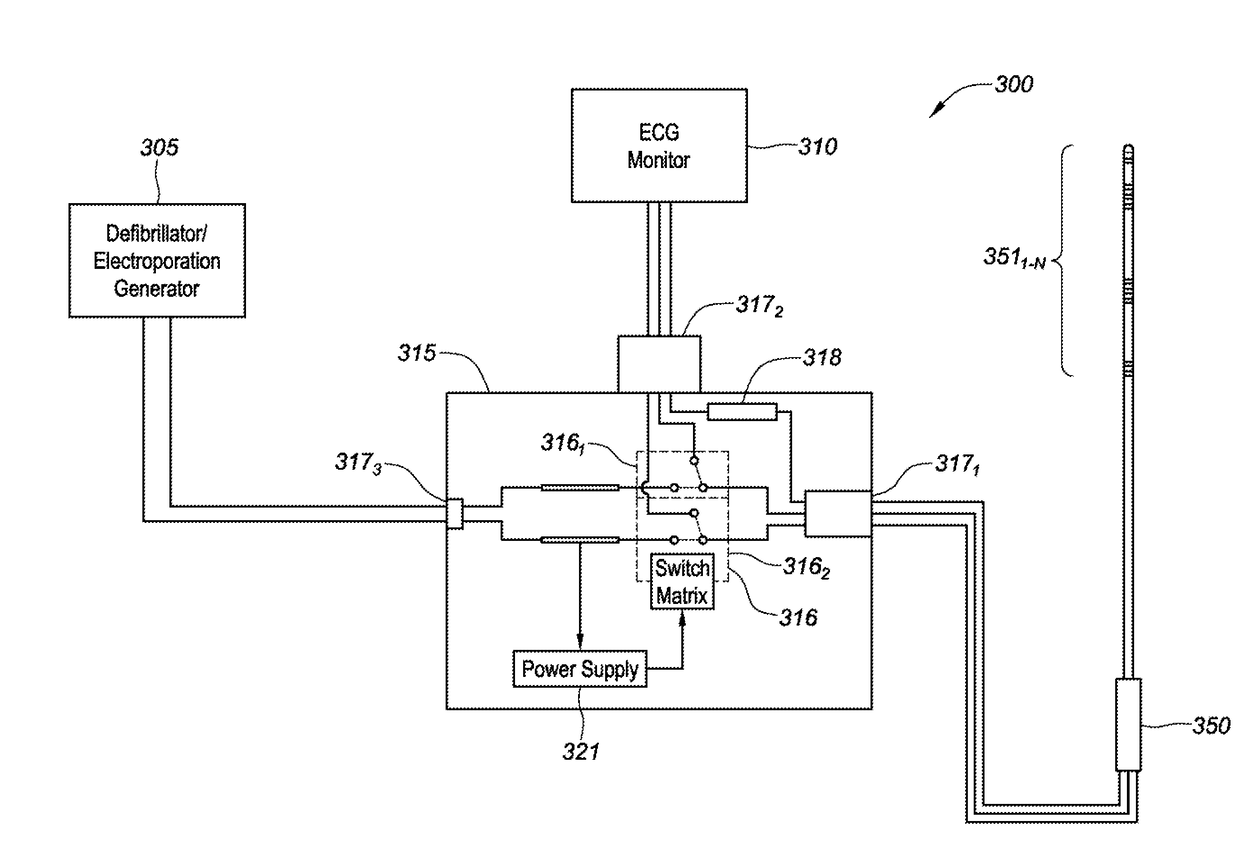
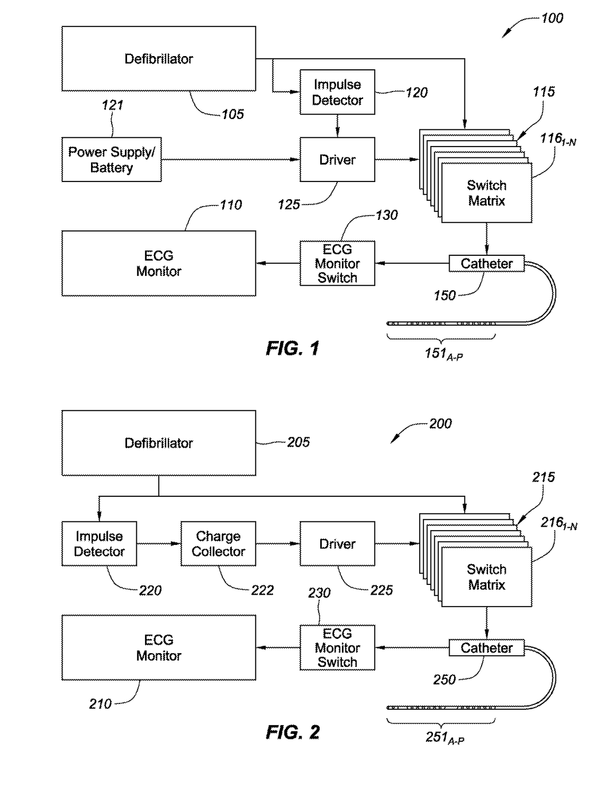
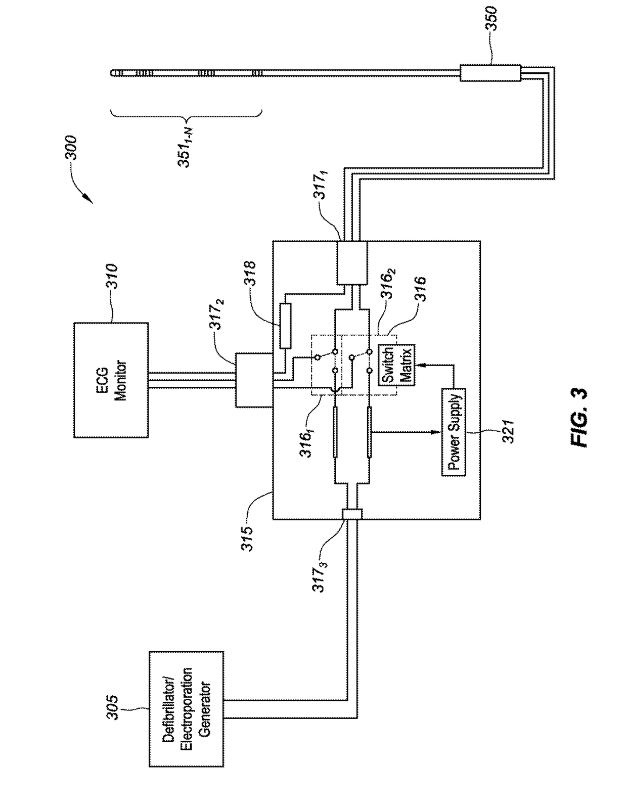
[0020]Aspects of the present disclosure are directed to an electronic switchbox for automatically switching between a receive and transmit functionality. In one embodiment, the instant disclosure relates to an electronic switchbox that automatically switches between receiving electrocardiograph signals and transmitting cardioversion impulses. Yet other embodiments of the present disclosure are directed to switching between receiving electrocardiograph signals and transmitting direct current, irreversible electroporation impulses. While various embodiments of the present disclosure are described in relation to cardiac applications, such embodiments are provided for exemplary purposes and are not intended to limit the scope of the present disclosure.

[0021]Aspects of the present disclosure are directed to both powered and unpowered electronic switchboxes. In unpowered implementations, the switchbox includes electrical circuitry that detects a defibrillator impulse signal, charges the s...


PUM


Abstract

Aspects of the present disclosure are directed to an electronic switchbox for automatically switching between receive and transmit functionalities. In one embodiment, an electronic switchbox automatically switches between receiving electrocardiograph signals and transmitting cardioversion impulses.

Description

CROSS-REFERENCE TO RELATED APPLICATIONS[0001]This application claims the benefit of U.S. Provisional Application No. 62 / 454,345, filed 3 Feb. 2017, the entire disclosure of which is incorporated by reference herein in its entirety.BACKGROUNDa. Field[0002]The instant disclosure relates to an electronic switchbox for automatically switching between receive and transmit functionalities. In one embodiment, the instant disclosure relates to an electronic switchbox that automatically switches between receiving electrocardiograph signals and transmitting cardioversion impulses.b. Background Art[0003]In cardiovascular cardioversion and irreversible electroporation therapies, electrodes at a distal end of a cardiovascular catheter may be utilized to both conduct a therapy and provide electrophysiological diagnostic information to the clinician. For example, the electrodes at the distal end of the catheter may provide diagnostic data by way of electrocardiograph signals (also referred to as E...

Claims


Application Information

Patent Timeline
Patent Type & Authority Applications(United States)
IPC IPC(8): A61B18/14A61B5/042A61B18/12A61N1/39H03K17/687A61B5/296
CPCA61B18/1492A61B5/0422A61B18/1206A61N1/3956A61N1/3987H03K17/6871A61B2018/00577A61B2018/00642A61B2018/00839A61B2018/00351A61B2018/0094A61B2018/1266A61B2018/00613A61B5/4836A61B2560/0219A61B2562/166A61N1/3962A61B2018/1293A61B5/287
Inventor BLANCK, ARTHUR GERALDBEDNAREK, MICHAEL C.TEODORU, SEBASTIAN
Owner ST JUDE MEDICAL CARDILOGY DIV INC
Why Eureka
Try Eureka