Viscous damper

a technology of viscous damper and damper body, which is applied in the direction of shock absorbers, mechanical equipment, vibration suppression adjustments, etc., can solve the problems of large mass of an anti-vibration system including the hub-side member, inability to increase the mass ratio with the inertia mass, and inability to greatly displace the inertia mass, etc., to achieve high vibration damping and easy assembly

Inactive Publication Date: 2018-08-16
FUKOKU CO LTD
View PDF14 Cites 2 Cited by
  • Summary
  • Abstract
  • Description
  • Claims
  • Application Information

AI Technical Summary

Benefits of technology

[0007]An object of the present invention is to provide a viscous damper having high vibration damping. Further, another object thereof is to provide the viscous damper that is easily assembled and in which it is difficult for a slid seal(s) to peel off and fall and / or abrade even if the viscous damper is used over a long period of time.

Problems solved by technology

Further, since the inertia mass needs to be covered with the case, mass of an anti-vibration system including the hub-side member becomes large, and a mass ratio with the inertia mass cannot be increased.
However, if the elastic member for seal to be mounted between the inertia mass and the hub-side member in order to prevent such leakage has a great contact force, the inertia mass cannot be greatly displaced with respect to the hub-side member and a great shear force cannot be applied to the damping liquid enclosed between the hub-side member and the inertia mass, so that great vibration attenuation due to the shear resistance of the damping liquid cannot be expected.
Additionally, if the elastic member for seal has a high pressurization force, a press-fitting resistance of the elastic member for seal becomes high, and the outer mass type viscous damper becomes difficult to assemble.
For this reason, if the contact force of the elastic member for seal is weakened for permitting slipping, a holding force of the inertia mass due to the elastic member becomes weak, so that the inertia mass irregularly swings greatly during the vibration, and there is a possibility that deterioration in local abrasion and / or vibration damping of the elastic member for seal will occur.

Method used


Image

  • Viscous damper
  • Viscous damper
  • Viscous damper

Examples


Embodiment Construction

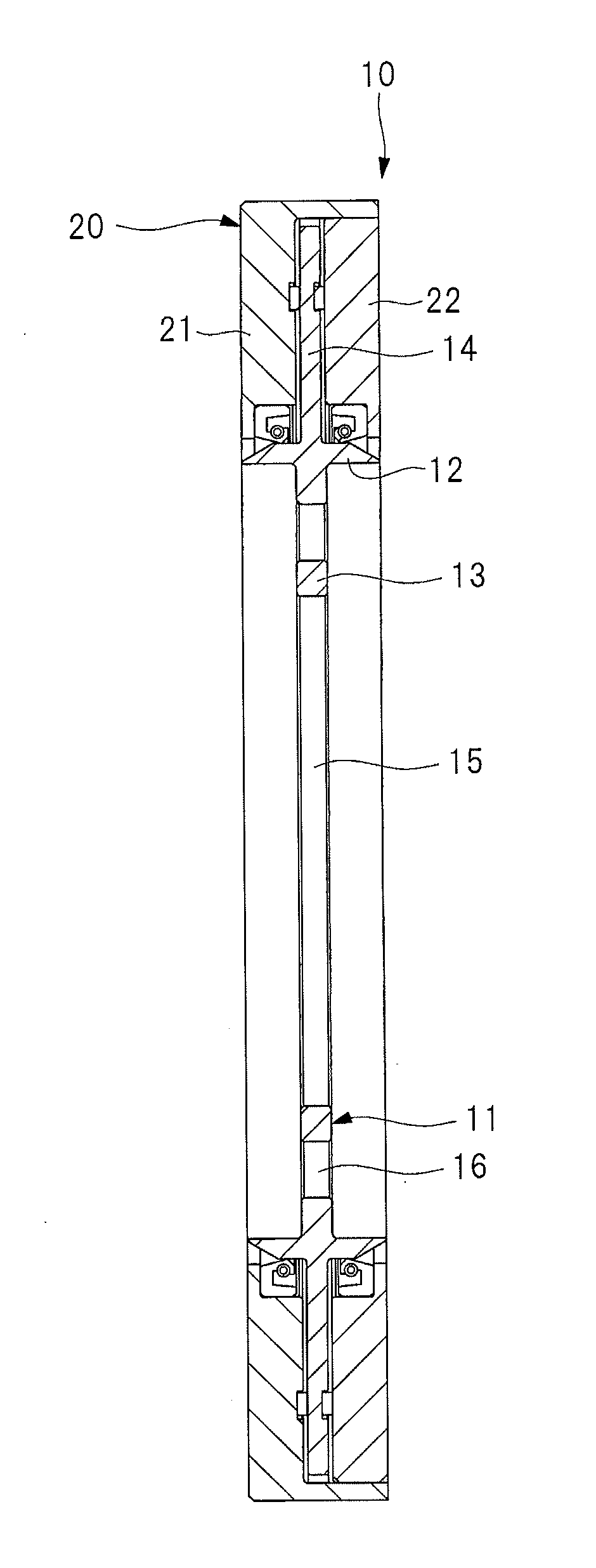
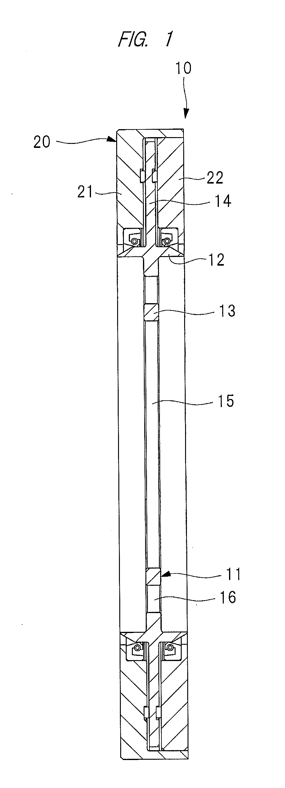
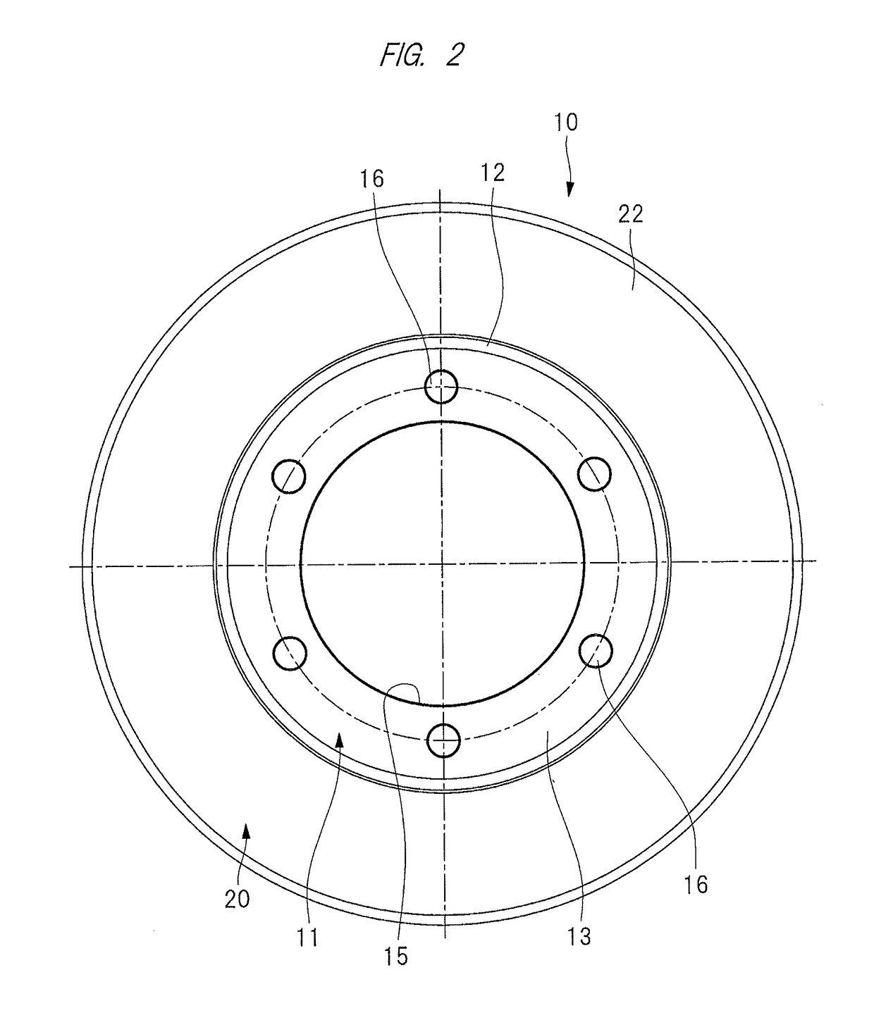
[0015]Hereinafter, an embodiment according to the present invention will be detailed based on the accompanying drawings. A viscous damper 10 shown in FIGS. 1 and 2 has a disk-shaped hub-side member, i.e., a hub plate 11. The hub plate 11 is mounted on a not-shown rotation axis such as a crank shaft and a camshaft in an engine used as a power source of a vehicle such a car, a truck, and a bus or / and a power source of an industrial machine such as a construction machine. The hub plate 11 has a plate base 13 whose outer periphery portion is provided integrally with a cylinder portion 12. The cylinder portion 12 protrudes axially from both surfaces of the plate base 13. A flange 14 protrudes radially outward from an axial middle part of the cylinder portion 12, and the flange 14 becomes integrated with the cylinder portion 12.

[0016]The hub plate 11 is provided with: a through-hole 15 into which the rotation axis is inserted; and a plurality of attachment holes 16 into which not-shown bo...


PUM


Abstract

A viscous damper 10 has a hub plate 11 mounted on a rotation axis, the hub plate 11 is provided with a cylinder portion 12 protruding axially, and the flange 14 protrudes radially outward from the cylinder portion. An inertia mass body 20 arranged outside the flange 14 includes a first annular inertia member 21 and a second annular inertia member 22, and a journal bearing 20 is arranged between the inertia mass body 20 and the flange 14. An inner periphery portion of the first annular inertia member 21 is provided with a first slid seal 41 for sealing damping liquid, and an inner periphery portion of the second annular inertia member 22 is provided with a second slid seal 42 for sealing the damping liquid L.

Description

CROSS-REFERENCE TO RELATED APPLICATIONS[0001]This application is a National Stage application of International Patent Application No. PCT / JP2016 / 072849, filed on Aug. 3, 2016, which claims priority to Japanese Patent Application Number 2015-156003, filed on Aug. 6, 2015, each of which is hereby incorporated by reference in its entirety.TECHNICAL FIELD[0002]The present invention relates to a viscous damper that is attached to a rotation axis such as a crank shaft in an internal combustion engine and absorbs torsional vibration of the rotation axis.BACKGROUND ART[0003]Each of internal combustion engines, i.e., engines used in a power source of a vehicle such as a car, a truck, and a bus and a power source of an industrial machine such as a construction machine and an agricultural machine has a rotation axis such as a crank shaft and a camshaft. Torsional vibration, i.e., rotational pulsation occurs on the rotation axis due to combustion of fuel. A torsional damper is mounted on the ro...

Claims


Application Information

Patent Timeline
Patent Type & Authority Applications(United States)
IPC IPC(8): F16F15/173F16F9/36F16F15/16
CPCF16F15/173F16F15/165F16F15/167F16F2222/12F16F2230/30
Inventor MATSUMOTO, SHIGEYUKI
Owner FUKOKU CO LTD
Why Eureka
Try Eureka