

Turbine engine turbine rotor with ventilation by counterbore
- Summary
- Abstract
- Description
- Claims
- Application Information
AI Technical Summary
Benefits of technology
Problems solved by technology
Method used
Image

Examples
Embodiment Construction
[0048]The embodiments described hereafter relate most particularly to the case of a low-pressure turbine, comprising a series of distributors (or stators) alternating along the axis X of rotation with a series of movable disks (or rotor). This is not limiting, however, in that the turbine could comprises a different number of states, and that the invention can also be applied in a high-pressure turbine, which can be single- or multistage.
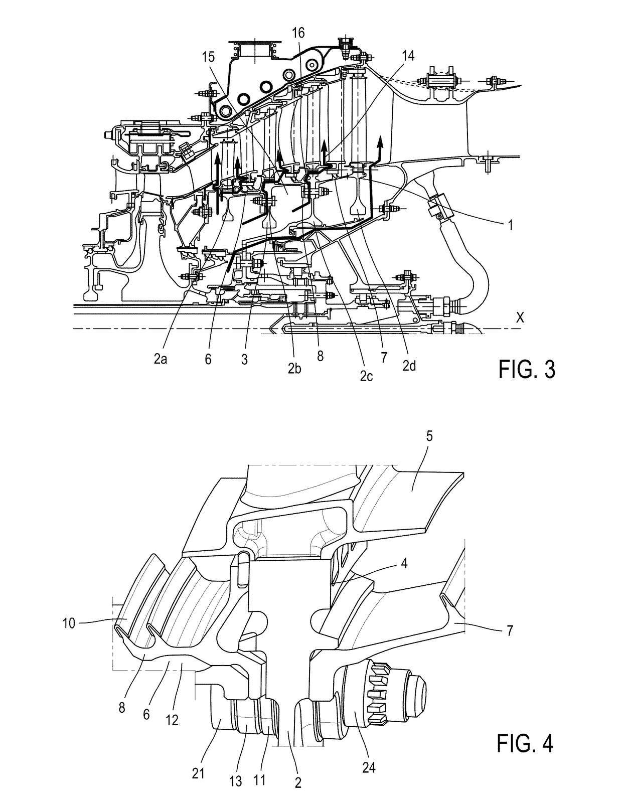
[0049]With reference to FIG. 3, the turbine conventionally includes one or more stages, each consisting of a distributor followed by a rotor 1 (or impeller).
[0050]The rotor 1 has an axis X of revolution which corresponds to a main axis of the turbine engine and comprises several disks 2, for example four disks 2, each comprising a hub 3 extending radially inward in the direction of the axis X. Peripheral grooves such as the cells 4, in which the movable blades 5 are slotted, are formed in a rim of the hubs 3.
[0051]In the entire present text, upstrea...
PUM
 Abstract
Description
Claims
Application Information