Distributed compressed air energy storage with heat network

Pending Publication Date: 2018-08-23
UMEZ ERONINI ERONINI IHEANYI
View PDF12 Cites 6 Cited by
  • Summary
  • Abstract
  • Description
  • Claims
  • Application Information

AI Technical Summary

Benefits of technology

The patent text discusses the use of compressor technology to store energy in compressed air. The text describes how intercoolers and aftercoolers are used to lower the temperature of the air and improve compression efficiency, reducing the amount of air needed to be stored. The text also mentions various techniques to improve efficiency and capacity, such as cooling the air during compression and heating it during expansion. However, these methods result in energy loss because heat generation and utilization are separated in time. The text also notes that long-term thermal energy storage is inefficient and dependent on the air pressure capacity of the system. Overall, the patent text highlights the technical problem of energy loss during air storage and proposes a solution to this problem.

Problems solved by technology

However both cooling of the compressed air during compression and heating it during expansion represent significant loss of energy because the heat generation and heat utilization are essentially separated in-time to off-peak hours and peak demand hours.
The use of equally consolidated long-term thermal energy storage which is fraught with inefficiencies is only marginally effective in alleviating the energy loss.
Also the electrical energy generation per unit of air storage capacity is dependent on the compressed air supply pressure and consolidated or underground (aquifer) air storage systems have limited pressure capacity due to physical considerations.

Method used


Image

  • Distributed compressed air energy storage with heat network
  • Distributed compressed air energy storage with heat network
  • Distributed compressed air energy storage with heat network

Examples


Embodiment Construction

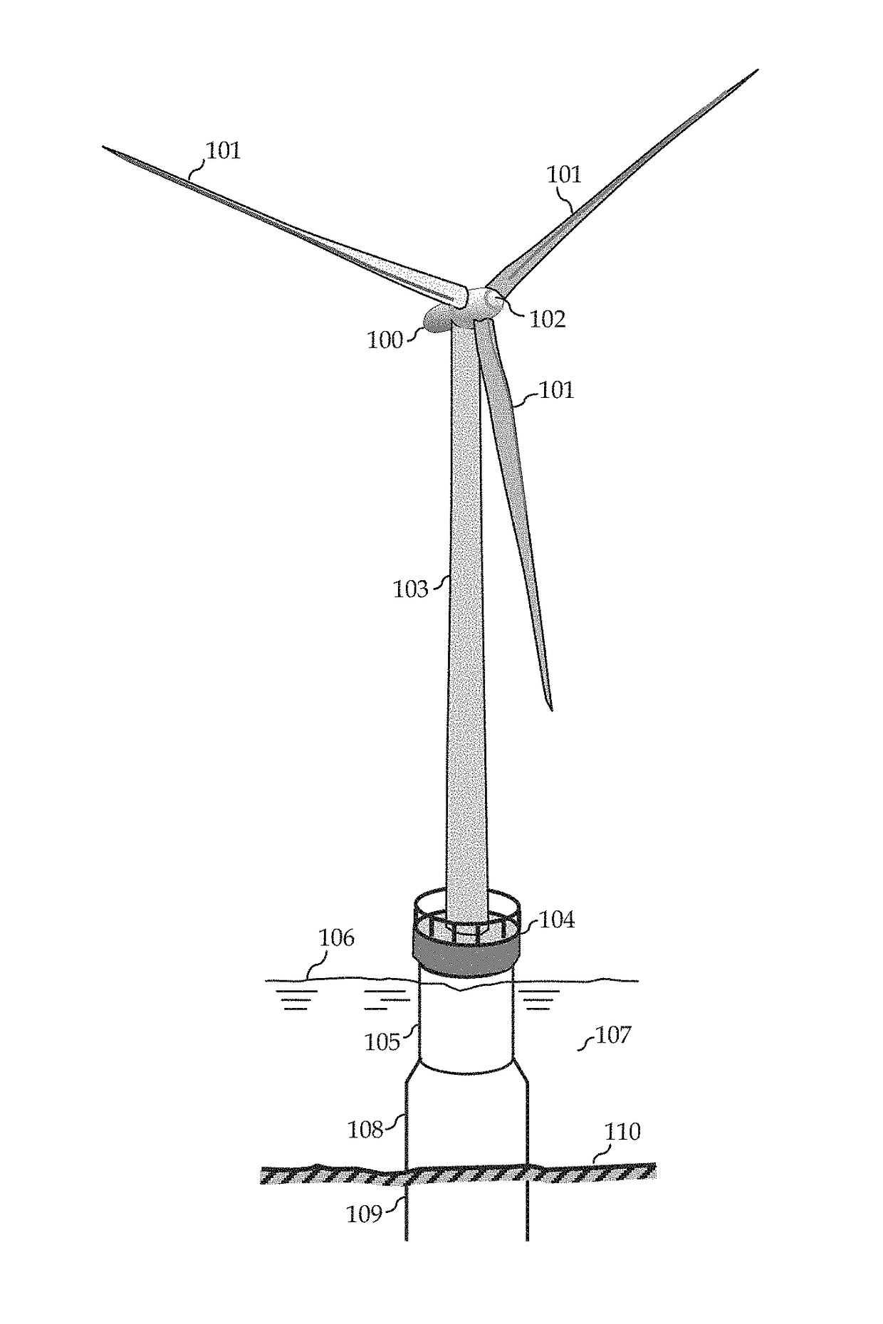
[0013]FIG. 1 depicts generally an individual wind turbine out of the many that would compose a wind farm. In the figures, like numerals indicate like or corresponding components throughout. Accordingly, the offshore wind turbine components include the turbine which consists of the nacelle 100, the rotor with the blades 101, and the hub 102. The rotor is connected through a drive train to the generator which is housed in the nacelle. Various sensors and control actuators such as for pitch and yaw controls (not shown) may be included in the nacelle and hub. The nacelle, blades and hub are mounted at the top of the tower 103, which incorporates a platform 104, connected to a transition piece 105, The platform is disposed sufficiently above the sea surface 106, but part of the transition piece 105 is typically below the sea surface and in the water 107. The transition piece connects to the foundation structure, a type of which is the monopile 108 illustrated in the figure. A sufficient ...


PUM


Abstract

A method and system of distributed Compressed Air Energy Storage with thermal energy interchange network of cooling and heating circuits and dynamically scheduled power production, energy storage and power generation from storage, of integrated individual power resources to enhance system thermal efficiency and capacity factor.

Description

TECHNICAL FIELD[0001]The invention relates generally to a method and system to improve the capacity factor of energy resources characterized by distributed intermittent power sources, such as wind turbines in a wind farm, by thermally efficient energy storage in compressed air. More specifically the invention relates to distributed compressed air energy storage with a heat interchange network for high thermal efficiency.BACKGROUND ART[0002]Intermittency and availability of wind and related energy resources are typically at variance with power demand resulting in under-utilization and modest intrinsic capacity factors for such power sources. The problem of intermittency and availability of some energy resources may be mitigated by incorporation of energy storage systems to accumulate energy during off-peak power demand and release the energy during peak power demand. Compressed Air Energy Storage devices store energy by using an electric motor to compress air which is then stored and...

Claims


Application Information

Patent Timeline
IPC IPC(8): F03D9/18F03D9/17F03D7/04F03D9/25F03D13/25
CPCF03D9/18F03D9/17F03D7/048F03D9/257F03D13/25F05B2240/95F05B2260/205F05B2270/1033F05B2270/303E02B17/0004E02B2017/0091Y02E10/727Y02E10/72Y02E60/16Y02E70/30
Inventor UMEZ-ERONINI, ERONINI IHEANYI
Owner UMEZ ERONINI ERONINI IHEANYI
Why Eureka
Try Eureka