Electric resistance welded stainless clad steel pipe and method of manufacturing the same

a technology of stainless clad steel and welded steel, which is applied in the direction of manufacturing tools, shaping tools, other domestic objects, etc., can solve the problems of increased production cost and reduced productivity, and achieve excellent weld characteristics

Inactive Publication Date: 2018-08-30
JFE STEEL CORP
View PDF2 Cites 8 Cited by
  • Summary
  • Abstract
  • Description
  • Claims
  • Application Information

AI Technical Summary

Benefits of technology

[0013]However, the techniques described in Patent Literature 1 to 3 each require, after electric resistance welding, an additional welding process, such as cutting away cladding material beads and performing build-up welding (Patent Literature 1), melting and solidifying with a TIG arc heat source or build-up welding along the weld seam portion (Patent Literature 2), or build-up welding the unwelded butting portions (Patent Literature 3). Therefore, productivity is decreased, the production cost is increased, and the additional build-up welding badly affects the environment, all of which are problems.
[0014]In certain embodiments of the present invention an electric resistance welded stainless clad steel pipe which has excellent weld characteristics, even without performing an additional welding process that is required in existing techniques after electric resistance welding, and a method of manufacturing the same, is provided.
[0015]The excellent weld characteristics include mainly excellent fracture characteristics, good weld shape, and excellent corrosion resistance.
[0016]It has been determined, in the case where a shielding gas is blown over portions to be welded of an open pipe from directly above the portions to be welded in the region extending from the heating starting point to the welding point at the edges of the open pipe without covering the above region with a shield box, the oxygen concentration around the portions to be welded can be markedly decreased by properly controlling the nozzle height i.e., the height from the upper ends of the portions to be welded to a shielding-gas outlet of a shielding-gas blowing nozzle, as well as the flow rate of the shielding gas to be blown; and also by configuring the shielding-gas blowing nozzle to be divided into three or more layers in the circumferential direction of the open pipe and by properly controlling the ratio between the flow rate of the blown gas at the gas outlet of two side layers and the flow rate of the blown gas at the gas outlet of the remaining layers.
[0027]According to embodiments of the present invention, it is possible to manufacture an electric resistance welded stainless clad steel pipe which has excellent weld characteristics, even without performing an additional welding process that is required in existing techniques after electric resistance welding.

Problems solved by technology

Therefore, productivity is decreased, the production cost is increased, and the additional build-up welding badly affects the environment, all of which are problems.

Method used


Image

  • Electric resistance welded stainless clad steel pipe and method of manufacturing the same
  • Electric resistance welded stainless clad steel pipe and method of manufacturing the same
  • Electric resistance welded stainless clad steel pipe and method of manufacturing the same

Examples


example 1

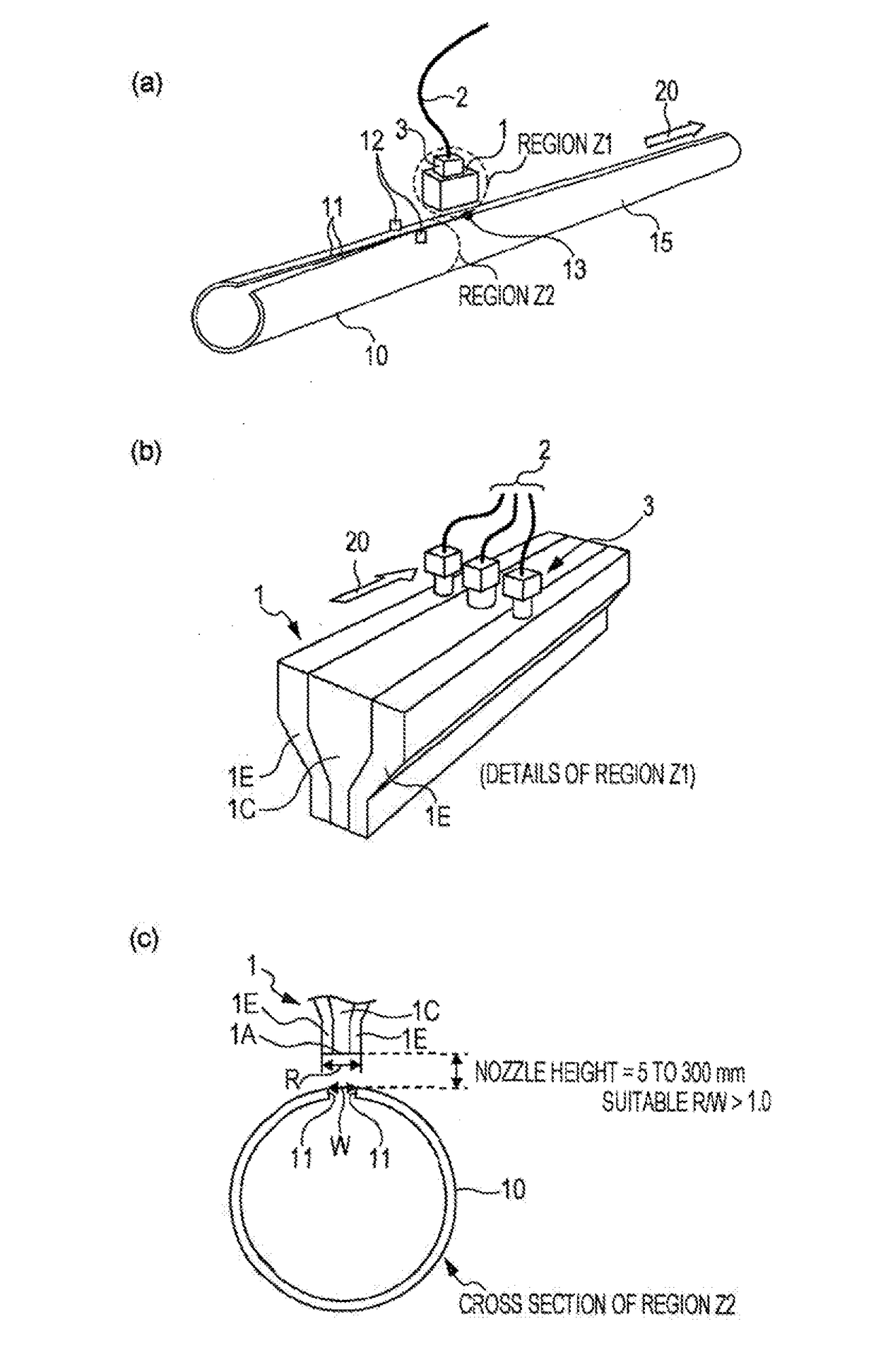
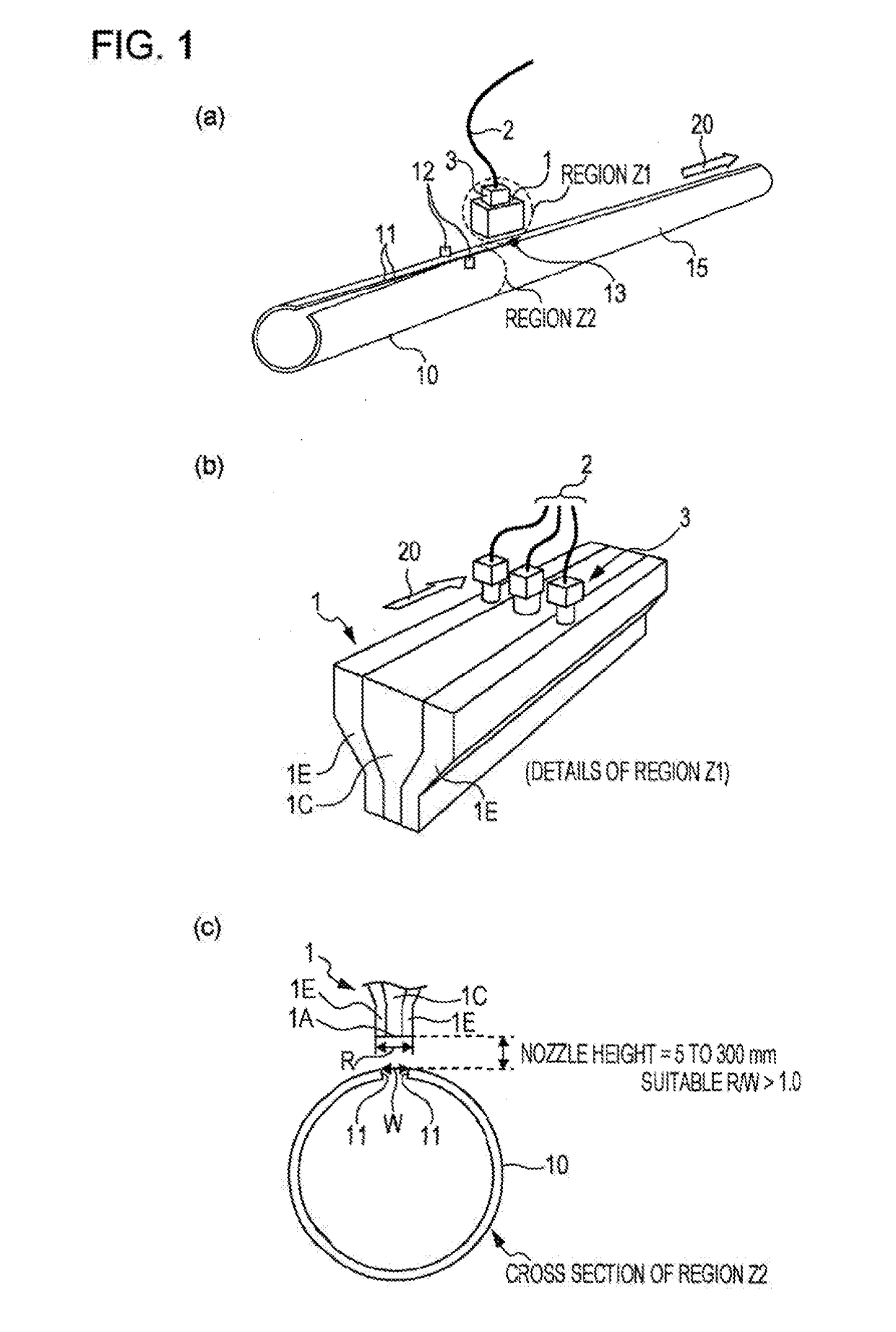
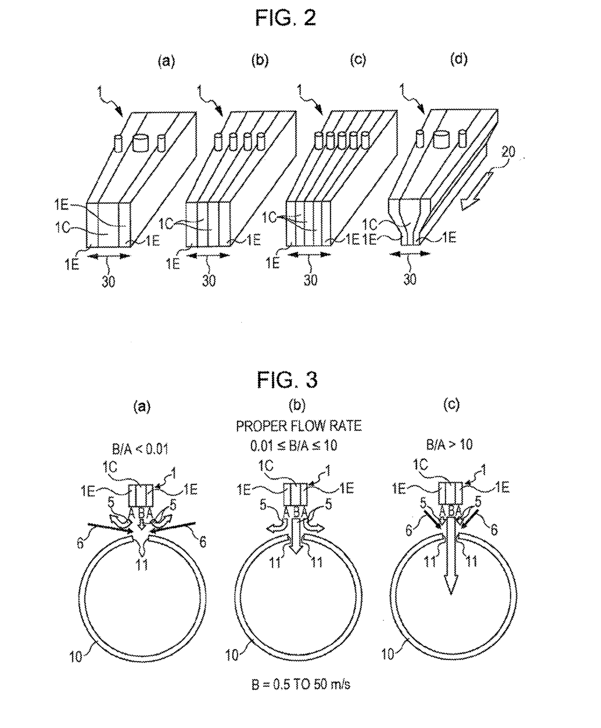
[0067]Electric resistance welded stainless clad steel pipes with an outer diameter of 300 mm were manufactured by a method in which stainless clad steel sheets including a cladding material made of stainless steel (SUS316, SUS304, SUS310, or SUS429) with a thickness of 2 mm on the pipe inner-surface side and a base metal made of low-carbon low-alloy steel (0.05 mass % C-0.3 mass % Si-1.2 mass % Mn—Fe) with a thickness of 5 mm on the pipe outer-surface side were used as a material, and the stainless clad steel sheets were passed through a pipe-making system including an uncoiler, a leveler, a roll former, an electric resistance welding machine, and a sizer arranged in this order. In the manufacturing process, during electric resistance welding, gas shielding for portions to be welded was performed by varying level of the gas blowing conditions and the amount of upset within or outside the ranges of embodiments of the present invention described in the embodiment as shown in Tables 1 ...


PUM

PropertyMeasurementUnit
widthaaaaaaaaaa
lengthaaaaaaaaaa
thicknessaaaaaaaaaa

Abstract

Provided are an electric resistance welded stainless clad steel manufactured by forming a hot-rolled steel strip of clad steel including low-carbon low-alloy steel and stainless steel into a cylindrical shape, and electric resistance welding the edges of the hot-rolled steel strip, characterized in that the flattening characteristic of an electric resistance weld, as-welded, satisfies the formula h / D<0.3, wherein h is the flattened height at fracture (mm) and D is the outer diameter of the pipe (mm), and a method of manufacturing the same.

Description

CROSS REFERENCE TO RELATED APPLICATIONS[0001]This is the U.S. National Phase application of PCT / JP2016 / 000850, filed Feb. 18, 2016, which claims priority to Japanese Patent Application No. 2015-048966, filed Mar. 12, 2015, the disclosures of these applications being incorporated herein by reference in their entireties for all purposes.TECHNICAL FIELD OF THE INVENTION[0002]The present invention relates to an electric resistance welded stainless clad steel pipe and a method of manufacturing the same, and more particularly relates to an electric resistance welded stainless clad steel pipe which, as-welded, has excellent weld characteristics and a method of manufacturing the same.BACKGROUND OF THE INVENTION[0003]In general, an electric resistance welded steel pipe is manufactured by a method in which a steel sheet (also referred to as a “steel strip”) is formed into a cylindrical shape, and the opposing edges in the width direction of the steel strip are heated and melted by a high-freq...

Claims


Application Information

Patent Timeline
Patent Type & Authority Applications(United States)
IPC IPC(8): B21C37/08B23K11/06B23K11/087
CPCB21C37/08B23K11/062B23K11/0873B23K11/36B23K2203/04B23K13/046B23K2103/04B23K2201/06B23K2201/10B23K13/025B23K2101/06B23K2101/10B23K13/06B23K13/00B23K13/02F16L9/02B21D37/08
Inventor OKABE, TAKATOSHIGOTO, SOTAHASHIMOTO, YUJIKATO, YASUSHIMATSUMOTO, ATSUSHIIDE, SHINSUKEOTA, HIROKI
Owner JFE STEEL CORP
Why Eureka
Try Eureka