Crack sensor including polymer for healing cracks and electronic device including the same

a crack sensor and crack technology, applied in semiconductor/solid-state device testing/measurement, instruments, material analysis, etc., can solve the problems of sensitivity decline, sensitivity and stability decline, and difficulty in detecting accurate signals, so as to achieve low manufacturing cost of the device, simple manufacturing process, and simple structure

Active Publication Date: 2018-08-30
IND ACADEMIC COOPERATION FOUND OF AJOU UNIV +1
View PDF0 Cites 3 Cited by
  • Summary
  • Abstract
  • Description
  • Claims
  • Application Information

AI Technical Summary

Benefits of technology

[0010]In one embodiment of the first aspect, when external energy is applied to the polymer layer, the restoring force of the polymer layer is increased.
[0011]In one embodiment of the first aspect, when at least one of heat, light, and electric energy is applied to the polymer layer, the restoring force of the polymer layer is increased.
[0022]The crack sensor according to one embodiment of the present disclosure includes the healing polymer, thereby maintaining the durability of the crack sensor by inhibiting crack growth and reducing the width of the crack using the healing polymer. Due to its high durability, the present crack sensor may be applied to flexible electronic circuit devices with integrated electronic circuits, electronic devices inserted into living bodies, and complex mechanical systems.
[0024]Furthermore, by irradiating the sensor with additional external energy, the crack healing capability may be improved. Localized external energy may be applied to heal the local area. The external energy is not limited to a specific healing mechanism, and various types of energies may be applied.
[0025]Further, since the present device is a device having a simple structure, the manufacturing cost of the device is low, and the manufacturing process thereof is very simple, and mass production thereof is possible.

Problems solved by technology

However, recently developed flexible sensors are difficult to detect accurate signals due to their low sensitivity.
However, due to the structural effect of the crack, the stress accumulates, and the crack deepens, and, eventually, the sensitivity decreases.
Particularly, after about 1,000 repeated tests, the cracks become deep or broken, resulting in a decrease in sensitivity and stability.

Method used


Image

  • Crack sensor including polymer for healing cracks and electronic device including the same
  • Crack sensor including polymer for healing cracks and electronic device including the same
  • Crack sensor including polymer for healing cracks and electronic device including the same

Examples


example 1

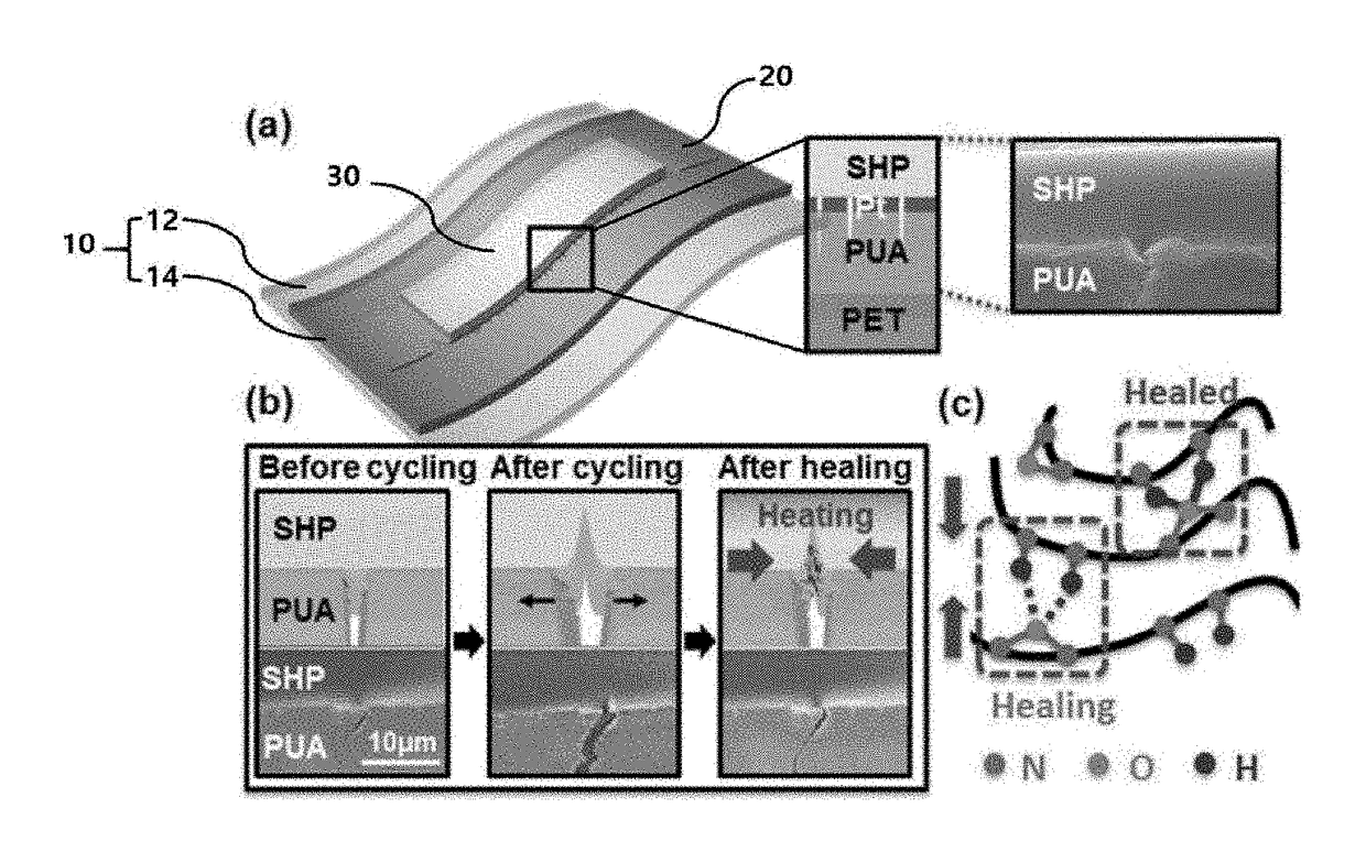
[0071]The restoring force of the healing polymer is created via the hydrogen bond of the functional group formed by the reaction between diacid (Empol 1016, Shijiazhuang Shuliang Commerce Trade Co., Ltd., China) and diamine (diethyelenetriamine).

[0072]First, 41.5 g of Empol 1016 and 17 g of diethyelenetriamine were reacted together under argon vapor at 160-degree C. for 24 hours. Thereafter, 1.5 g of the reaction product is collected. The collected reaction product and 200 mg of urea were reacted with each other at 135-degree C. for 6 hours. As a result, a healing polymer was prepared.

[0073]Furthermore, a 10 μm thick PUA (poly-urethane acrylate) as a soft polymer layer was applied on 50 μm PET (polyethylene terephthalate) as a base layer. On the soft polymer layer, platinum Pt is deposited to a thickness of 20 nm to obtain a stack. Thereafter, the stack was bent using a rod having a curvature of 1 mm to generate cracks to produce a crack sensor. A self-healing polymer (SHP) was coat...

example 2

[0080]To test the performance of a sensor including the healing polymer, a sensor of the present invention including the healing polymer and a conventional sensor were compared to each other.

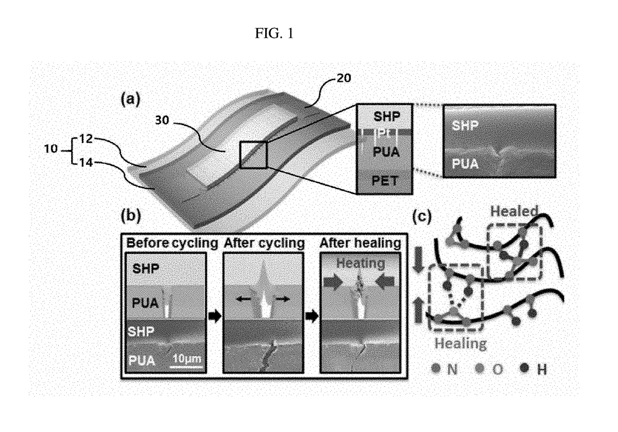
[0081]Specifically, the sensor manufactured in the example 1 was subjected to 25,000 repetitive tests by applying a force at a rate of 50 mm / min at a strain of 2%, which is the operating range of the sensor. Thereafter, healing was performed three times at an external temperature of 50 DEG C. for 10 minutes. The sensitivity of the sensor is measured, and the result graph is shown in FIG. 2a. For comparison, a repetitive test on a conventional sensor was performed in the same manner, and, then, the sensitivity thereof was measured, and the resulting graph was added to FIG. 2b.

[0082]As shown in FIGS. 2a and 2b, in the case of the conventional sensor, the sensitivity decreased gradually after 1,000 repeated tests. On the contrary, in the case of the sensor having the healing polymer, its sensitivi...

example 3

[0083]To confirm that the sensitivity is recovered, additional experiments were conducted to confirm the change in base resistance affecting the sensitivity. The base resistance value was measured for a crack sensor (self-healing sensor) manufactured in Example 1 and a conventional sensor employed as a comparison example. The results are shown in FIG. 3.

[0084]The restoration of the sensitivity is due to the nature of the base resistance returning to its original value after repeated testing. Depending on the recovery of the base resistance, it is determined whether the sensitivity is restored. As shown in FIG. 3, in the case of the conventional sensor, after repeated testing, the base resistance continued to increase. However, in the case of the sensor including the self-healing polymer, the base resistance returned to the original state after the healing process.


PUM

PropertyMeasurementUnit
thickaaaaaaaaaa
thickaaaaaaaaaa
thicknessaaaaaaaaaa

Abstract

A crack sensor with crack healing is provided. The sensor having: a substrate; a conductive layer disposed on the substrate, wherein the conductive layer contains cracks formed therein; and a polymer layer disposed between the substrate and the conductive layer, or disposed on the conductive layer and not between the substrate and the conductive layer; wherein a restoring force of the polymer layer suppresses further growth of the cracks or restores cracks.

Description

CROSS-REFERENCE TO RELATED APPLICATION[0001]This application claims the benefit of Korean patent application No. 10-2017-0024828 filed Feb. 24, 2017, the entire content of which is incorporated herein by reference for all purposes as if fully set forth herein.FIELD OF THE INVENTION[0002]The present disclosure relates to crack sensors, including healing polymers, that are configured to heal cracks and inhibit crack growth, and electronic devices including such sensors.BACKGROUND OF THE INVENTION[0003]The importance of sensors that can read mechanical stimuli in biometric integrated electronic devices or flexible integrated electronic circuits that detect sophisticated bio-signals or detect minute stresses is increasing. However, recently developed flexible sensors are difficult to detect accurate signals due to their low sensitivity.[0004]To solve this sensitivity problem, a crack sensor has been developed which simulates the crack structure of a spider's vibrating sensory organs. Th...

Claims


Application Information

Patent Timeline
Patent Type & Authority Applications(United States)
IPC IPC(8): G01R31/28H01L21/66
CPCG01R31/2896H01L22/34G01R31/2817G01R31/2858H01L22/20C08L101/12G01N27/70G01N2203/0067
Inventor KIM, TAE ILKANG, DAE SHIKPARK, BYEONG HAK
Owner IND ACADEMIC COOPERATION FOUND OF AJOU UNIV
Why Eureka
Try Eureka