Artificial photosynthesis module

a photosynthesis module and artificial technology, applied in the direction of electrolysis process, electrode with substrate and coating, electrolysis components, etc., can solve the problems of poor electrolysis efficiency, decrease in electrolysis efficiency, and poor electrolysis efficiency, and achieve excellent energy conversion efficiency

Inactive Publication Date: 2018-09-13
FUJIFILM CORP +1
View PDF0 Cites 3 Cited by
  • Summary
  • Abstract
  • Description
  • Claims
  • Application Information

AI Technical Summary

Benefits of technology

[0044]According to the invention, the artificial photosynthesis module having excellent energy conversion efficiency can be obtained.

Problems solved by technology

Therefore, there is a problem that the efficiency of electrolysis is bad.
For this reason, there is a problem that water stagnates on the surfaces and the efficiency of the electrolysis decreases.
For this reason, there is a problem that the electrolytic solution stagnates on the surfaces and the efficiency of the electrolysis decreases.
However, the form of the electrodes for generating electrolyzed water with respect to the flow of the pure water to be supplied is not considered at all.
For this reason, there is a problem that the pure water to be supplied stagnates in the electrodes for generating electrolyzed water and the efficiency of the electrolysis decreases.
Additionally, in JP2006-213932A, there is a problem that a power source for applying a voltage is required between the electrodes for generating electrolyzed water.

Method used


Image

  • Artificial photosynthesis module
  • Artificial photosynthesis module
  • Artificial photosynthesis module

Examples


example 1

[0438]Hereinafter, the effects of the artificial photosynthesis module of the invention will be described in detail.

[0439]In the present example, in order to confirm the effects of the electrode configuration of the invention, artificial photosynthesis modules of Examples Nos. 1 to 7 and Comparative Example No. 1 illustrated below were made.

[0440]In the present example, the artificial photosynthesis modules of Example Nos. 1 to 7 and Comparative Example No. 1 were controlled by a potentiostat such that the current densities of a hydrogen generation electrode and an oxygen generation electrode became 8.13 mA / cm2 while the electrolytic aqueous solution AQ was supplied thereto. Changes in electrolysis voltage were measured from the start of the control, and electrolysis voltages (V) after 10 minutes were obtained. Then, the electrolysis voltages (V) after 10 minutes were set to representative values of the electrolysis voltages of the artificial photosynthesis modules. The results are ...

example no.1

Example No. 1

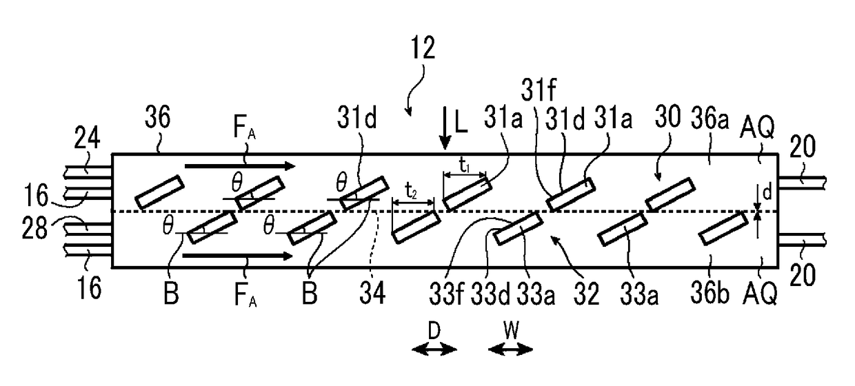
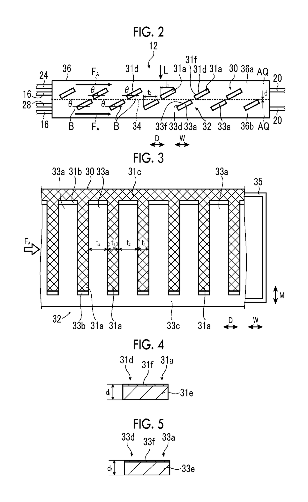
[0445]In an artificial photosynthesis module of Example No. 1, a hydrogen generation electrode and an oxygen generation electrode are comb-type electrodes. Electrodes (Exeload EA: JAPAN CARLIT CO., LTD.) obtained by performing platinum plating treatment of a thickness of 1 μm on the surface of a base material made of titanium were used for the hydrogen generation electrode and the oxygen generation electrode.

[0446]In the hydrogen generation electrode and the oxygen generation electrode, respectively, in a state where the entire electrodes are in a flat-plate-shaped state, the electrode dimensions are 32 mm×120 mm×Thickness 1.0 mm, comb teeth have Width 3 mm×Length 32 mm×Number of teeth 15, and the width between the comb teeth is 5 mm. In a state where the entire electrodes are in a flat-plate-shaped state, the gap spacing of the hydrogen generation electrode and the oxygen generation electrode in a state where the comb teeth of the hydrogen generation electrode and the ...

example no.2

Example No. 2

[0450]An artificial photosynthesis module of Example No. 2 has the same configuration as Example No. 1 except that the flow rate of the electrolytic aqueous solution AQ is 1.0 liter / min, as compared to Example No. 1. For this reason, the detailed description thereof will be omitted.


PUM

PropertyMeasurementUnit
tilt angleaaaaaaaaaa
widthaaaaaaaaaa

Abstract

In an artificial photosynthesis module, a plurality of first electrode portions of a hydrogen generation electrode are disposed side by side with a gap, and each of a plurality of second electrode portions of an oxygen generation electrode is disposed at a gap between the first electrode portions of the hydrogen generation electrode as seen from the hydrogen generation electrode side with respect to the diaphragm. A first photocatalyst layer of at least one first electrode portion of the hydrogen generation electrode or a second photocatalyst layer of at least one of the second electrode portions of the oxygen generation electrode is tilted with respect to a flow direction of an electrolytic aqueous solution, or a projecting part is provided on a surface of the first photocatalyst layer of at least one first electrode portion of the hydrogen generation electrode or a surface of the second photocatalyst layer of at least one second electrode portion of the oxygen generation electrode.

Description

CROSS-REFERENCE TO RELATED APPLICATIONS[0001]This application is a Continuation of PCT International Application No. PCT / JP2016 / 083711 filed on Nov. 14, 2016, which claims priority under 35 U.S.C. § 119(a) to Japanese Patent Application No. 2015-233014 filed on Nov. 30, 2015, Japanese Patent Application No. 2016-085980 filed on Apr. 22, 2016 and Japanese Patent Application No. 2016-086028 filed on Apr. 22, 2016. Each of the above applications is hereby expressly incorporated by reference, in its entirety, into the present application.BACKGROUND OF THE INVENTION1. Field of the Invention[0002]The present invention relates to an artificial photosynthesis module that decomposes an electrolytic aqueous solution into hydrogen and oxygen with light, and particularly, to an artificial photosynthesis module having electrodes in which a photocatalyst layer of an electrode portion is tilted with respect to a direction in which an electrolytic aqueous solution flows.2. Description of the Relate...

Claims


Application Information

Patent Timeline
Patent Type & Authority Applications(United States)
IPC IPC(8): C25B11/02C25B1/10C25B1/00C25B9/08C25B11/04C25B9/19
CPCC25B11/02C25B1/10C25B1/003C25B9/08C25B11/0405Y02E60/36C25B1/55C25B1/04C25B9/73C25B9/19C25B9/70C25B11/051
Inventor YOSHIDA, SATOSHINAGATE, HIROSHI
Owner FUJIFILM CORP
Why Eureka
Try Eureka