Converter valve

Active Publication Date: 2018-09-13
NR ELECTRIC CO LTD +2
View PDF0 Cites 5 Cited by
  • Summary
  • Abstract
  • Description
  • Claims
  • Application Information

AI Technical Summary

Benefits of technology

[0015]The converter valve provided in the embodiment of the present invention comprises: a top shielding cover, a bottom shielding cover, at least two vertically stacked valve layers, and a maintenance platform. The top shielding cover is disposed at an upper portion of an uppermost valve layer. The bottom shielding cover is disposed at a lower portion of a lowermost valve layer. Each of the valve layers comprises two valve modules disposed side-by-side in a horizontal direction. The two valve modules are electrically connected via a busbar and mechanically connected via securing connectors. A lower valve layer is connected to an upper valve layer in a suspended manner. A body of the maintenance platform is located between horizontal planes on which two vertically adjacent valve layers are located, or between horizontal planes on which the lowermost valve

Problems solved by technology

A converter valve is a critical component in high voltage direct current transmission (HVDC), and has a relatively bulky physical size.
For a split-level structure arrangement, 16 reinforced epoxy resin rods are required to construct a cage-type frame in space, and then various assemblies are sequentially secured at different locations of this cage-type frame, resulting in a very complicated structure and cumbersome installation and maintenance.
In addition, this cage-type frame has relatively poor shock resistance.
For an even-level structure arrangement, suspending insulators are used between an upper layer and a lower layer, no connection measures are taken between two assemblies within one valve layer, and the converter valve is configured to be two independent converter valves effectively, resulting in complex installation.
In addition, when external forces such as earthqu

Method used


Image

  • Converter valve
  • Converter valve
  • Converter valve

Examples


Embodiment Construction

[0022]The present invention is further illustrated in detail below with reference to particular embodiments and the accompanying drawings.

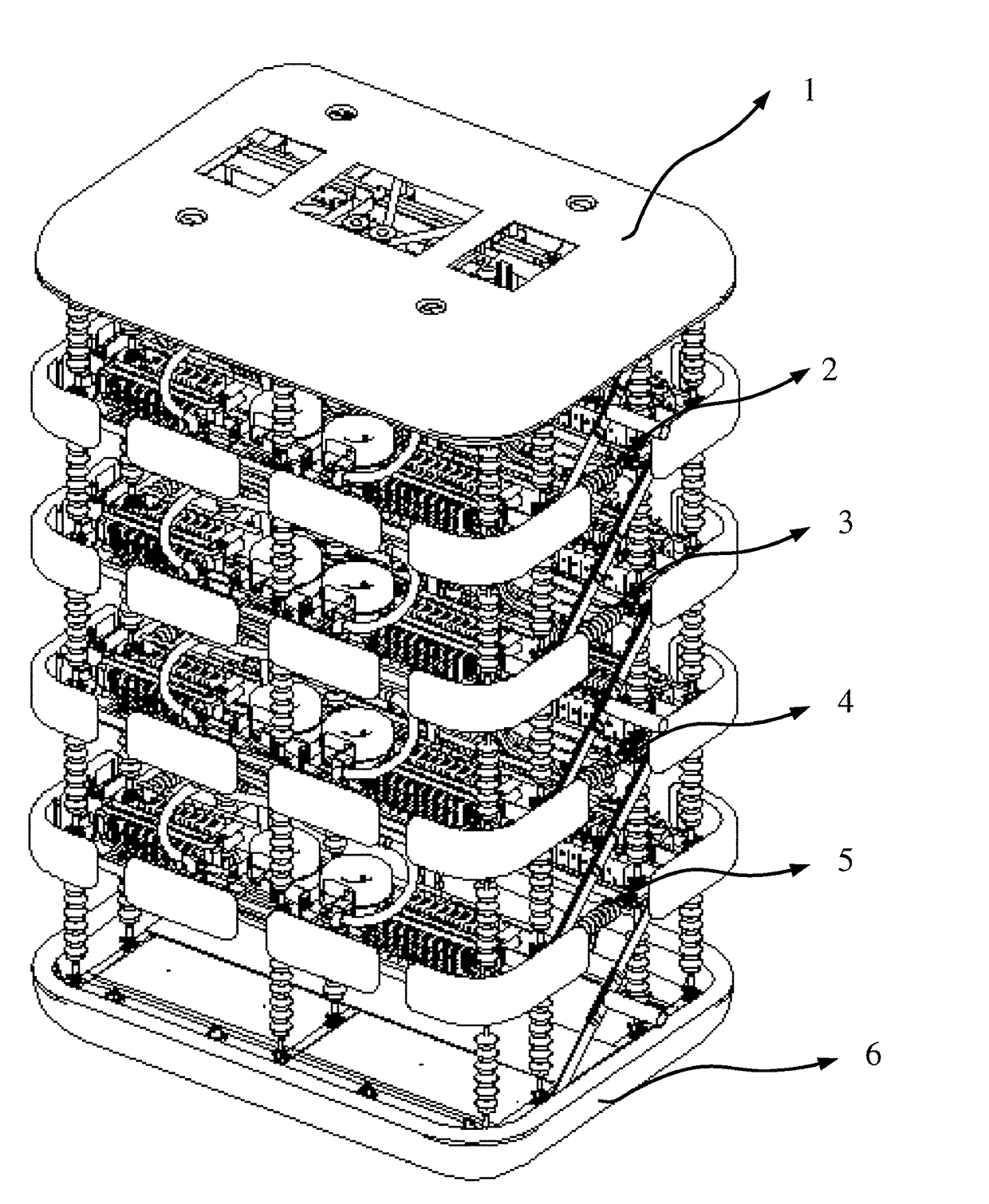
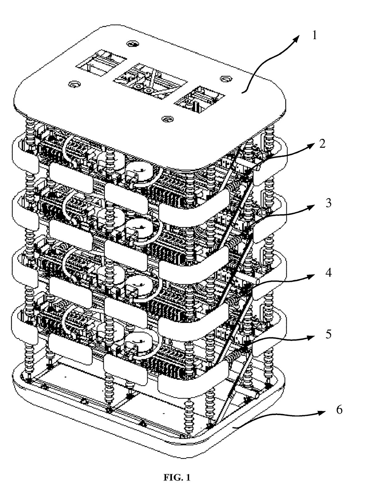
[0023]As shown in FIG. 1, in the application scenario, the converter valve consists of four vertically stacked valve layer 2-5 with a shielding cover 1 disposed on a top portion thereof and a shielding cover 6 disposed on a bottom portion thereof. The shielding cover plays a critical role in improving electric field distribution in a high voltage electric field.

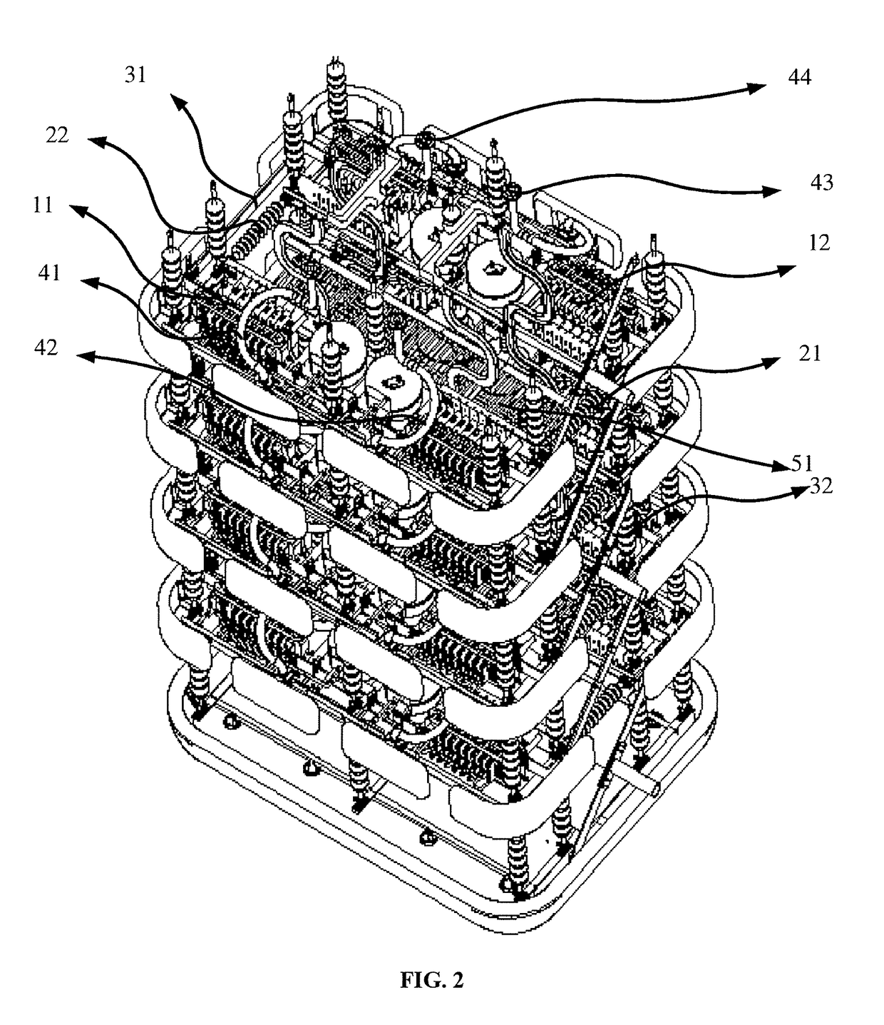
[0024]As shown in FIG. 3, an upper valve layer and a lower valve layer in the converter valve are connected in a suspended manner using twelve insulators 61, 62, 63, 64, 65, 66, 67, 68, 69, 610, 611, 612. Having suspended the valve layers using the insulators, the entire converter valve constitutes a flexible system from top to bottom. The valve layers can swing within a certain range without the overall structure being damaged when being subjected to strong external forces such as earthqua...


PUM


Abstract

A converter valve includes a top shielding cover, a bottom shielding cover, at least two vertically stacked valve layers, and a maintenance platform. The top shielding cover is disposed at an upper portion of an uppermost valve layer. The bottom shielding cover is disposed at a lower portion of a lowermost valve layer. Each of the valve layers comprises two valve modules disposed side-by-side in a horizontal direction. The two valve modules are electrically connected via a busbar and mechanically connected via securing connectors. A lower valve layer is connected to an upper valve layer in a suspended manner. A body of the maintenance platform is located between horizontal planes on which two vertically adjacent valve layers are located, or between horizontal planes on which the lowermost valve layer and the bottom shielding cover are located.

Description

BACKGROUND OF THE INVENTIONField of the Invention[0001]The present invention relates to the technical field of power electronics and power systems and, more particularly to a converter valve. Description of Related Art[0002]A converter valve is a critical component in high voltage direct current transmission (HVDC), and has a relatively bulky physical size. In operation, the converter valve is subjected to a voltage of several hundred kV at both ends, and is in the process of frequent switching on and off. At present, a single commercial power electronics withstands a voltage of up to 8.5 kV. Accordingly, it is necessary to connect dozens of or even nearly one hundred stages of the devices in series. A valve tower generally uses a structure with a plurality of valve layers sequentially stacked from top to bottom and thyristors evenly distributed on respective valve layers.[0003]One valve layer of the converter valve is generally composed of two valve modules. Currently, the two valv...

Claims


Application Information

Patent Timeline
IPC IPC(8): H02M7/00H02M1/00
CPCH02M7/003H01L25/072H01L25/115H01L25/117H05K7/14339H02M7/00
Inventor ZHANG, XIANGLIU, LEIFANG, TAIXUNCHEN, CHIHANLI, ZHAOLI, HAIYINGDING, FENGFENG
Owner NR ELECTRIC CO LTD
Why Eureka
Try Eureka