Reverse osmosis treatment apparatus and reverse osmosis treatment method

Inactive Publication Date: 2018-10-04
HITACHI LTD
View PDF3 Cites 4 Cited by
  • Summary
  • Abstract
  • Description
  • Claims
  • Application Information

AI Technical Summary

Benefits of technology

[0013]The present invention provides a reverse osmosis treatment apparatus and a reverse osmosis treatment method capable of keeping high the amount of water productio

Problems solved by technology

It is difficult to completely prevent fouling of reverse osmosis membranes even if the water to be treated is pretreated with chemicals or the like.
However, this method has a problem in that it is impossible to produce water by the reverse osmosis treatment with the membrane unit while cleaning, which reduces the operating ratio and thus the amount of water production.
In particular, in multiple-stage reverse osmosis treatment apparatuses as described in Patent Document 1, bio-fouling is more noticeable in the reverse osmosis membrane modules at the front stage in the case of performing the reverse osmosis treatment on water to be treated in which microorganisms are likely to grow, such as seawater and sewage treatment water.
However, while the reverse osmosis membrane modules at the front stage is being cleaned, the reverse osmosis membrane modules at the rear stage cannot be operated as in the ordinary operation, so that operation of one of the multiple membrane units is stopped to clean it, and the remaining membrane units are operated at a higher water production rate than in the ordinary operation.
However, for the

Method used


Image

  • Reverse osmosis treatment apparatus and reverse osmosis treatment method
  • Reverse osmosis treatment apparatus and reverse osmosis treatment method
  • Reverse osmosis treatment apparatus and reverse osmosis treatment method

Examples


Embodiment Construction

[0025]Hereinafter, descriptions will be provided for a reverse osmosis treatment apparatus and a reverse osmosis treatment method according to an embodiment of the present invention. Note that common constituents in the drawings below are denoted by the same reference signs, and repetitive descriptions thereof are omitted.

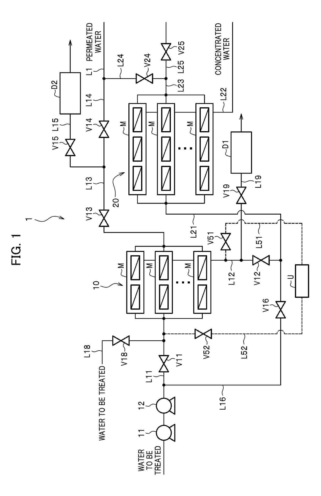
[0026]FIG. 1 is a diagram illustrating a configuration example of a reverse osmosis treatment apparatus according to an embodiment of the present invention.

[0027]As illustrated in FIG. 1, a reverse osmosis treatment apparatus 1 according to the present embodiment mainly includes multiple banks (10, 20), treatment water pipes (L11, L21), concentrated water pipes (L12, L22), permeated water pipes (L13, L23), a treatment water pipe valve (V11), a concentrated water pipe valve (V12), a permeated water pipe valve (V14), a bypass pipe (L16), and chemical cleaning pipes (L51, L52).

[0028]The banks (10, 20), each including reverse osmosis membrane modules M, form a membrane...


PUM


Abstract

A reverse osmosis treatment apparatus includes a membrane unit including an osmosis membrane module. The membrane unit includes a plurality of banks connected in series, each bank including an osmosis membrane module. At least one of the banks includes a treatment water pipe valve and a concentrated water pipe valve, and a bypass pipe capable of diverting the water to be treated, which is to be supplied to the bank, around the bank and draining the water to be treated and a chemical cleaning pipe capable of supplying the reverse osmosis membrane module disposed in the bank with chemical cleaning water are connected. A reverse osmosis treatment method is for cleaning intermittently a bank having the treatment water pipe valve and the concentrated water pipe valve while continuing the reverse osmosis treatment using the remaining bank.

Description

BACKGROUND OF THE INVENTION1. Field of the Invention[0001]The present invention relates to a reverse osmosis treatment apparatus to desalinate saltwater such as seawater by reverse osmosis and a reverse osmosis treatment method using the same.2. Description of the Related Art[0002]Reverse osmosis treatment apparatuses to desalinate saltwater by reverse osmosis have been used in various fields, such as desalination of seawater, reuse of wastewater, and production of pure water. A reverse osmosis treatment apparatus typically includes cylindrical reverse osmosis membrane modules. A reverse osmosis membrane module of this type includes multiple reverse osmosis membrane elements holding reverse osmosis membranes, inside a cylindrical pressure vessel.[0003]The reverse osmosis membrane element included in the cylindrical reverse osmosis membrane module has a structure in which the reverse osmosis membranes are spirally wound around a water collection pipe. The multiple reverse osmosis mem...

Claims


Application Information

Patent Timeline
IPC IPC(8): B01D65/02B01D61/02B01D61/08B01D61/12B01D63/06C02F1/44B01D65/06
CPCB01D65/027B01D61/022B01D61/08B01D61/12B01D63/063C02F1/441B01D65/06B01D2311/04B01D2313/46B01D2313/48B01D2321/02B01D2321/04B01D2321/162C02F1/004C02F1/5245C02F2103/08C02F2209/03C02F2301/08C02F2209/05Y02A20/131B01D61/06B01D63/10B01D65/02B01D2317/025B01D2317/04B01D2321/16C02F2209/06C02F2301/043C02F2303/16B01D61/026
Inventor FUKUZAKI, KOJIONISHI, MAKOTOYOSHIKAWA, SHINICHIYAMADA, SHUJIKITAMURA, KOTAROKONDO, YASUTAKA
Owner HITACHI LTD
Why Eureka
Try Eureka