
Fluorescence image analyzing apparatus, image processing method of fluorescence image, and computer program

a fluorescence image and analysis apparatus technology, applied in the field of fluorescence image analysis apparatus, an image processing method of fluorescence image, and a computer program, can solve the problems of operator and the like not being able to determine the bright spot, the bright spot may be different, and the dark spot cannot be detected, so as to improve the detection accuracy and the effect of dark spo

Active Publication Date: 2018-10-18
SYSMEX CORP
View PDF0 Cites 1 Cited by
  • Summary
  • Abstract
  • Description
  • Claims
  • Application Information

AI Technical Summary

Benefits of technology

The patent describes a method to make it easier for operators to recognize and detect bright spots in fluorescence images of cells. By enhancing the pixel values of dark spots in the image and reducing the difference between them and the light brilliance, the method makes it easier to identify and analyze fused bright spots that may occur in a composite image of multiple fluorescence images. This method improves the interpretation and analysis of bright spot images.

Problems solved by technology

However, even in the case where the same fluorescently labeled probe is used, the brightness may be different between bright spots in one fluorescence image due to variations in pretreatment.
Therefore, when an operator checks the presence or absence of a bright spot in the fluorescence image captured by a flow cytometer in the FISH method, there is a case where a darker bright spot cannot be detected.
Therefore, there is a problem that, when confirming a fused bright spot in a fluorescence image captured by using a flow cytometer in the multicolor FISH method, for example, in the case where a certain red bright spot is dark and a green bright spot adjacent thereto is bright, the red bright spot is overwhelmed by the green bright spot and the operator cannot determine that the bright spot is a fused bright spot when two fluorescence images are superimposed.

Method used


Image

  • Fluorescence image analyzing apparatus, image processing method of fluorescence image, and computer program
  • Fluorescence image analyzing apparatus, image processing method of fluorescence image, and computer program
  • Fluorescence image analyzing apparatus, image processing method of fluorescence image, and computer program

Examples


Embodiment Construction

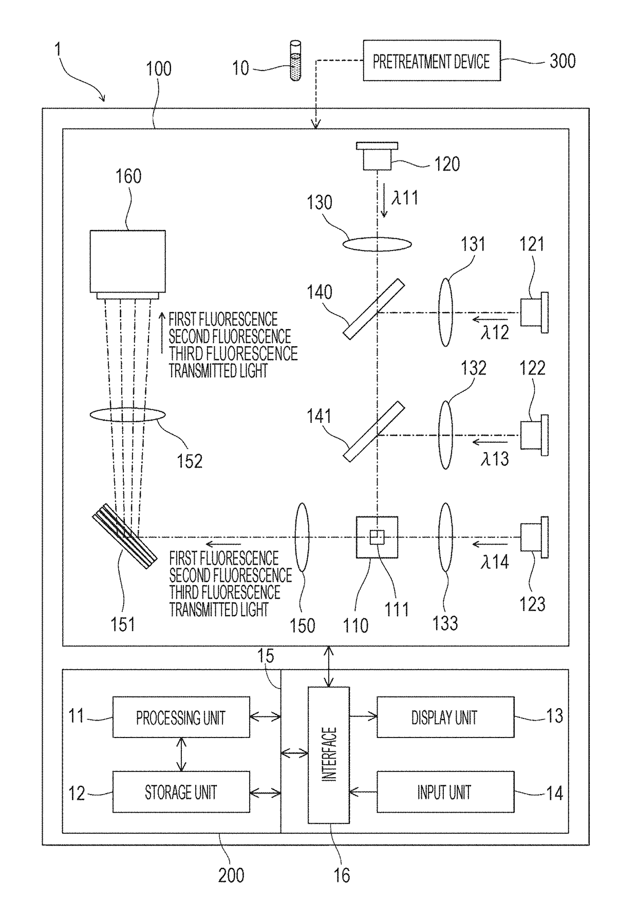
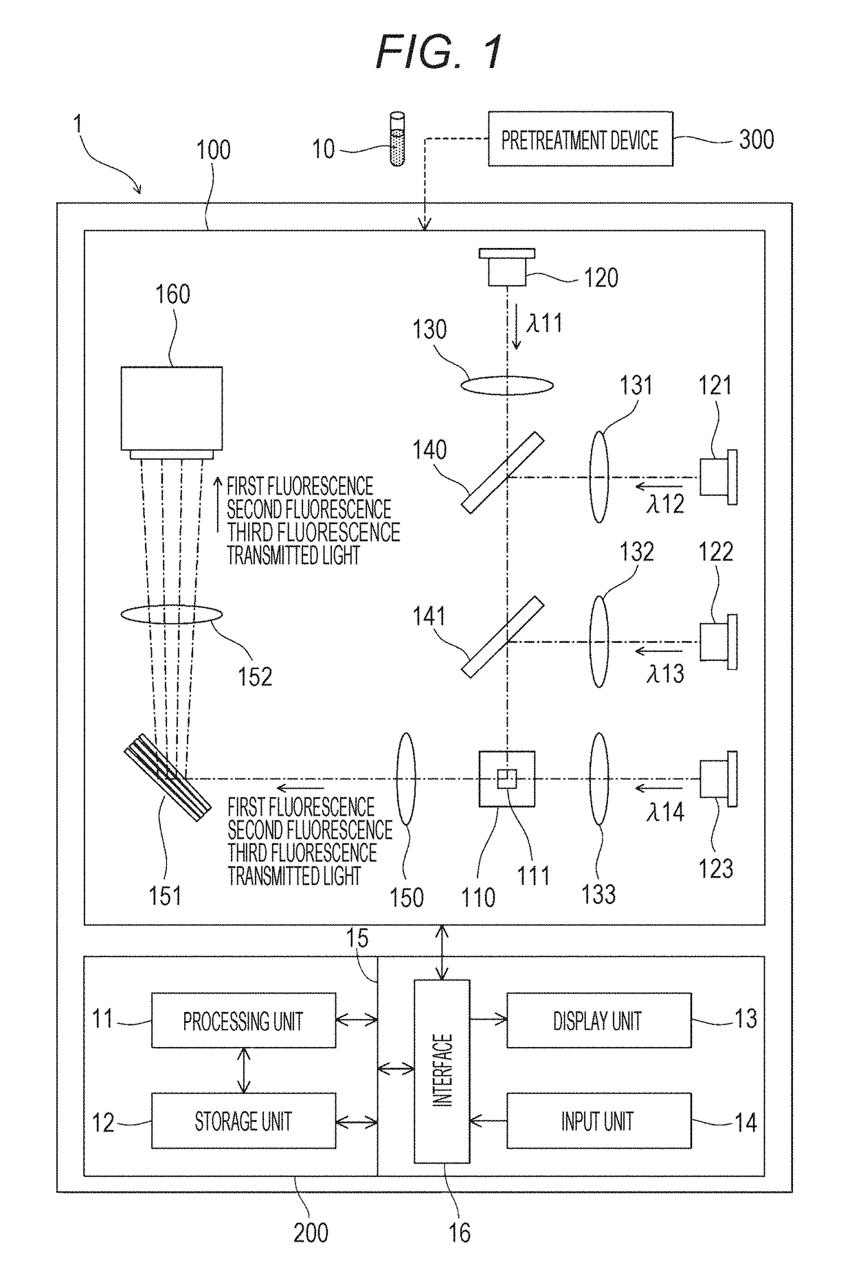
[0029]Hereinafter, embodiments of the present disclosure will be described in detail with reference to attached drawings. In the following embodiment, the present disclosure is applied to an apparatus in which a sample subjected to a pretreatment of hybridizing a target site (target sequence) present in the nucleus of a cell with a nucleic acid probe (hereinafter simply referred to as a probe) including a nucleic acid sequence having a sequence complementary to the target sequence and labeled with a fluorescent dye is measured and a fluorescence image acquired for each cell among a plurality of cells in the sample is analyzed.

[0030]In one example of this embodiment, analysis of chromosomal abnormalities by a fluorescence in situ hybridization (FISH) method is performed by, for example, a flow cytometer (e.g., imaging flow cytometer), a fluorescence microscope, or the like. In the following embodiment, as an example, an embodiment in which a BCR gene on chromosome 22 and an ABL gene ...


PUM

PropertyMeasurementUnit
fluorescence image analyzingaaaaaaaaaa
fluorescenceaaaaaaaaaa
fluorescence imageaaaaaaaaaa

Abstract

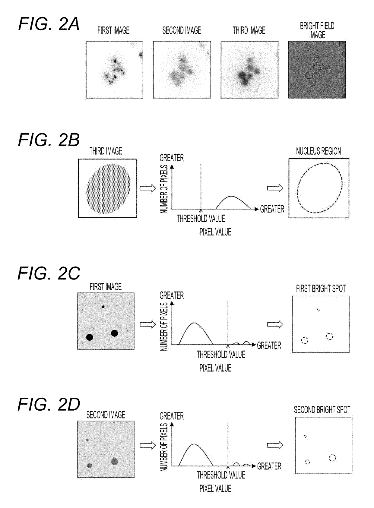
Disclosed is a fluorescence image analyzing apparatus including a light source that emits light to a sample including a plurality of cells labeled with a fluorescent dye at a target site, an imaging unit that captures a fluorescence image of each of the cells that emit fluorescence by being irradiated with the light, a processing unit that processes the fluorescence image captured by the imaging unit, and a display unit that displays the fluorescence image processed by the processing unit. The processing unit performs an extraction process of extracting, for each cell, a plurality of bright spots in the fluorescence image including the target site, a changing process of changing a pixel value of each of the plurality of extracted bright spots based on the pixel value of each bright spot, and a display process of displaying the fluorescence image whose pixel value is changed on the display unit.

Description

CROSS REFERENCE TO RELATED APPLICATIONS[0001]This application claims priority from prior Japanese Patent Application No. 2017-080851, filed on Apr. 14, 2017 entitled “FLUORESCENCE IMAGE ANALYZING APPARATUS, IMAGE PROCESSING METHOD OF FLUORESCENCE IMAGE, AND COMPUTER PROGRAM”, the entire contents of which are incorporated herein by reference.TECHNICAL FIELD[0002]The present invention relates to a fluorescence image analyzing apparatus, an image processing method of a fluorescence image, and a computer program.BACKGROUND[0003]WO 2003 / 048300 discloses a method for treating cells when a flow cytometer or the like is applied for detection in a fluorescence in situ hybridization method (FISH method). In the FISH method, first, a pretreatment for hybridizing a fluorescently labeled probe to the base sequence of a target site present in the nucleus of a cell is performed to fluorescently label the target site. Subsequently, a fluorescence signal (bright spot) generated from the fluorescentl...

Claims


Application Information

Patent Timeline
Patent Type & Authority Applications(United States)
IPC IPC(8): G01N21/64
CPCG01N21/6428G06T7/0012G01N2021/6439G01N21/6456G06T7/0002G06T2207/30024H04N23/55H04N23/80C12Q1/6841G01N2021/6441G06T2207/10024G06T2207/30072G06T2207/10064G06T2207/10056G02B21/0076G02B21/008G06T5/94
Inventor MATSUMOTO, SHOHEISHARMA, SHRUTI
Owner SYSMEX CORP
Learn More