
Hermetically sealed filtered feedthrough assembly having a capacitor with an oxide resistant electrical connection to an active implantable medical device housing

Active Publication Date: 2018-10-25
WILSON GREATBATCH LTD
View PDF6 Cites 11 Cited by
  • Summary
  • Abstract
  • Description
  • Claims
  • Application Information

AI Technical Summary

Benefits of technology

This patent is about a method of creating high purity hermetic terminals and structures for AIMDs using a combination of materials, including mating high purity alumina and pure platinum metal particles within a mixture of solvents and binders. This process avoids the use of braze materials to buffer the CTE mismatch between the two materials. The method also includes adjusting the solids loading, binder burnout, sintering and cool down parameters to create an intimate and tortuous interface between the alumina and platinum materials that is either a direct bond or an amorphous interfacial layer that can tolerate stress levels without losing hermeticity. The patent also describes a co-fired hermetically sealed feedthrough that includes a high purity alumina substrate with a via hole filled with a substantially closed pore, fritless platinum fill, and a hermetic seal between the platinum fill and the substrate, formed by a mutually conformal interface. This helps minimize damaging tensile stresses and ensures optimal performance.

Problems solved by technology

This is not possible when the via has a conductive wire inserted into the insulator via.

Method used


Image

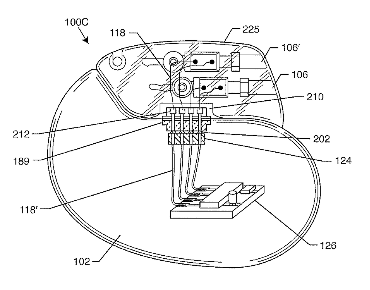
  • Hermetically sealed filtered feedthrough assembly having a capacitor with an oxide resistant electrical connection to an active implantable medical device housing
  • Hermetically sealed filtered feedthrough assembly having a capacitor with an oxide resistant electrical connection to an active implantable medical device housing
  • Hermetically sealed filtered feedthrough assembly having a capacitor with an oxide resistant electrical connection to an active implantable medical device housing

Examples


Embodiment Construction

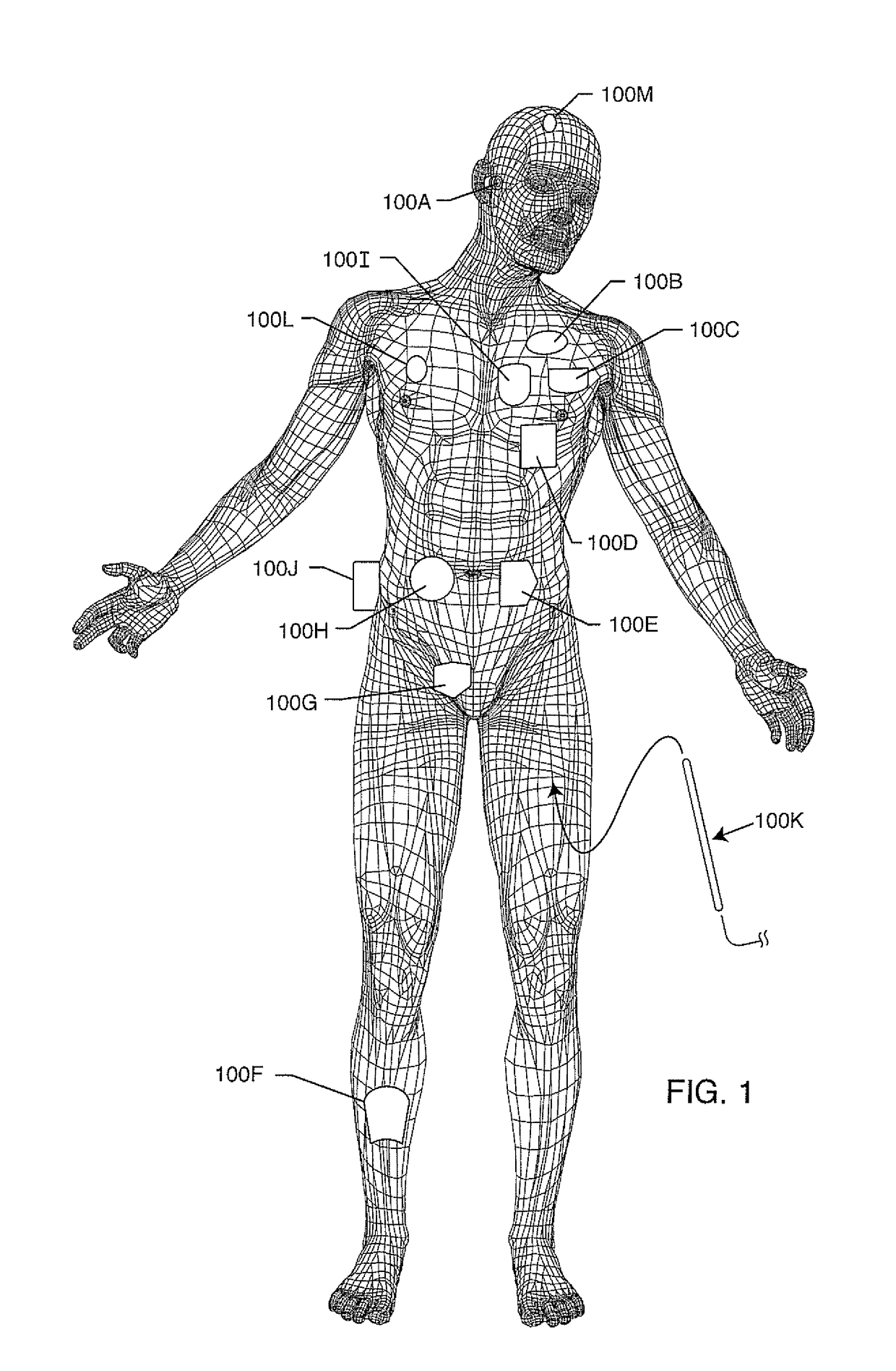
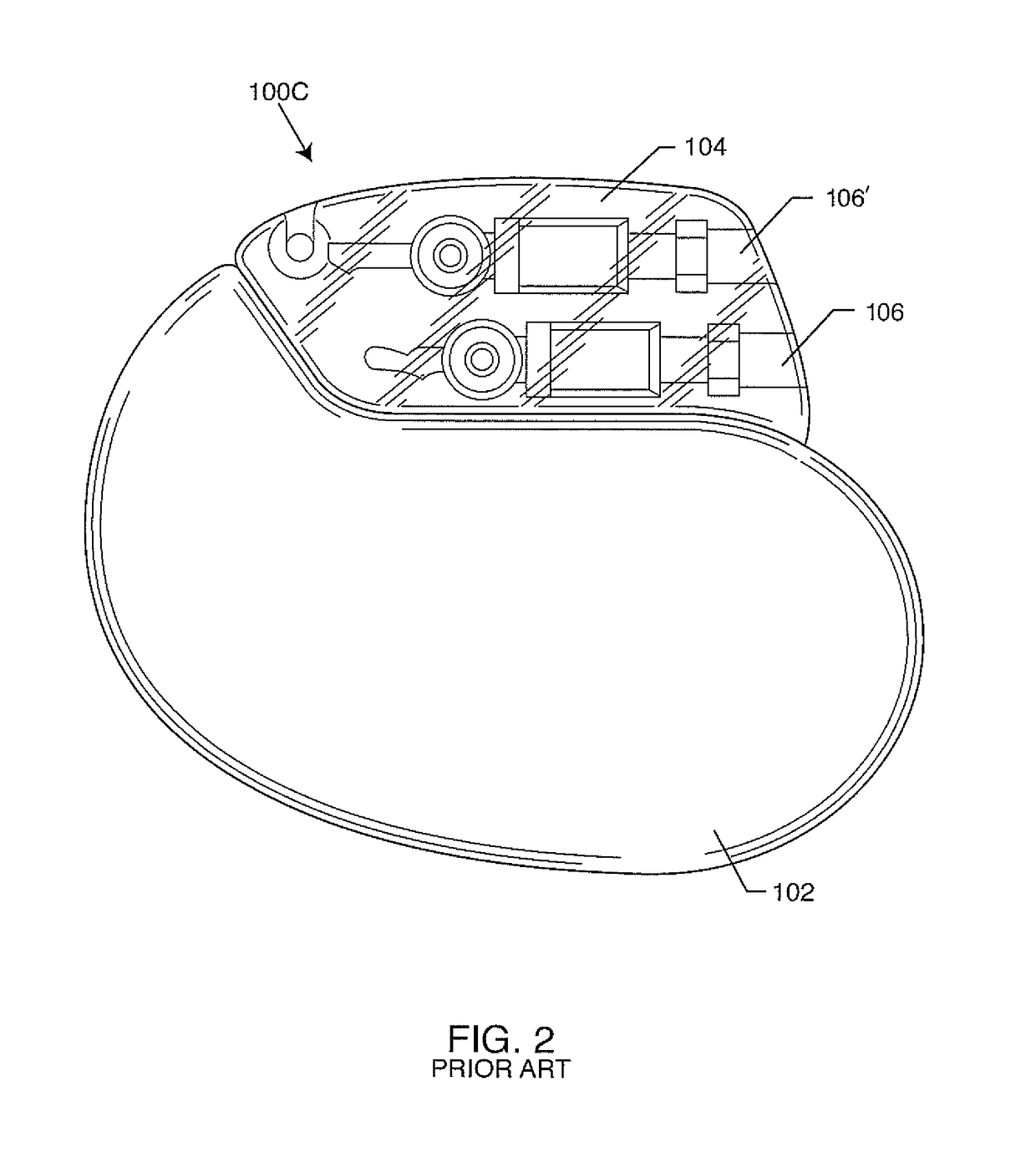
[0189]FIG. 1 illustrates various types of active implantable and external medical devices 100 that are currently in use. FIG. 1 is a wire formed diagram of a generic human body showing a number of implanted medical devices. 100A is a family of external and implantable hearing devices which can include the group of hearing aids, cochlear implants, piezoelectric sound bridge transducers and the like. 100B includes an entire variety of neurostimulators and brain stimulators. Neurostimulators are used to stimulate the Vagus nerve, for example, to treat epilepsy, obesity and depression. Brain stimulators are similar to a pacemaker-like device and include electrodes implanted deep into the brain for sensing the onset of a seizure and also providing electrical stimulation to brain tissue to prevent the seizure from actually happening. The lead wires that come from a deep brain stimulator are often placed using real time imaging. Most commonly such lead wires are placed during real time MRI...


PUM

PropertyMeasurementUnit
Fractionaaaaaaaaaa
Fractionaaaaaaaaaa
Dielectric polarization enthalpyaaaaaaaaaa

Abstract

A hermetically sealed filtered feedthrough assembly attachable to an AIMD includes an insulator hermetically sealing a ferrule opening of an electrically conductive ferrule with a gold braze. A co-fired and electrically conductive sintered paste is disposed within and hermetically seals at least one via hole extending in the insulator. At least one capacitor is disposed on the device side. An active electrical connection electrically connects a capacitor active metallization and the sintered paste. A ground electrical connection electrically connects the gold braze to a capacitor ground metallization, wherein at least a portion of the ground electrical connection physically contacts the gold braze. The dielectric of the capacitor may be less than 1000 k. The ferrule may include an integrally formed peninsula portion extending into the ferrule opening spatially aligned with a ground passageway and metallization of an internally grounded feedthrough capacitor. The sintered paste may be of substantially pure platinum.

Description

CROSS-REFERENCE TO RELATED APPLICATIONS[0001]The present patent application is a continuation-in-part of U.S. application Ser. No. 15 / 368,722, filed on Dec. 5, 2016, which is a continuation of U.S. application Ser. No. 14 / 600,401, now U.S. Pat. No. 9,511,220, which is a divisional of U.S. application Ser. No. 13 / 742,781, filed Jan. 16, 2013, now U.S. Pat. No. 8,938,309, which claims priority from U.S. App. Ser. Nos. 61 / 587,029, filed on Jan. 16, 2012; 61 / 587,287, filed on Jan. 17, 2012, and 61 / 587,373, filed on Jan. 17, 2012.[0002]The present patent application is also a continuation-in-part of U.S. application Ser. No. 15 / 863,194, filed on Jan. 5, 2018, which claims priority from U.S. App. Ser. No. 62 / 613,500, filed on Jan. 4, 2018, and which is a continuation-in-part of U.S. application Ser. No. 15 / 797,278, filed on Oct. 30, 2017, which claims priority from U.S. App. Ser. Nos. 62 / 552,363, filed on Aug. 30, 2017, 62 / 461,872, filed on Feb. 22, 2017, 62 / 450,187, filed on Jan. 25, 201...

Claims


Application Information

Patent Timeline
IPC IPC(8): A61N1/375H02G3/22H01R43/00A61N1/05A61N1/08H01G4/40H01G4/35H01G4/30H01G4/12H01G4/005H01G2/10C22C29/12B23K35/30A61N1/372B22F1/10
CPCA61N1/05A61N1/372H01G4/12H01G4/005A61N1/08H01R43/00C22C29/12H02G3/22H01G4/30B23K35/3013H01G2/103H01G4/35A61N1/3754Y10T156/1052A61N1/375H01G4/40B22F7/08B23K35/025B23K35/322H01G4/236H01R4/022H01R13/5224H01R13/719H01R2201/12B22F1/10
Inventor STEVENSON, ROBERT A.FRYSZ, CHRISTINE A.SEITZ, KEITH W.MARZANO, THOMASMARTINO, MARC GREGORY
Owner WILSON GREATBATCH LTD
Learn More