
Method of Assuring Dissolution of Degradable Tools

a technology of dissolvable tools and tools, which is applied in the field of assuring the dissolution of degradable tools, can solve the problems of increasing the cost and difficulty of intervention activities, affecting the quality of the earth, so as to improve the solvent dispersibility, and improve the effect of strength and conductivity

Inactive Publication Date: 2018-10-25
TERVES
View PDF33 Cites 22 Cited by
  • Summary
  • Abstract
  • Description
  • Claims
  • Application Information

AI Technical Summary

Benefits of technology

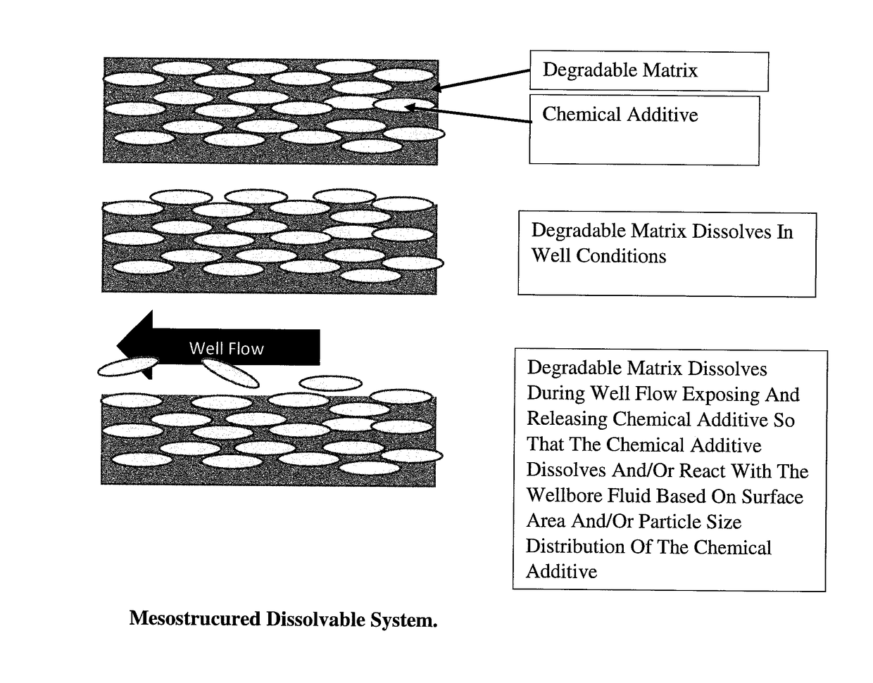
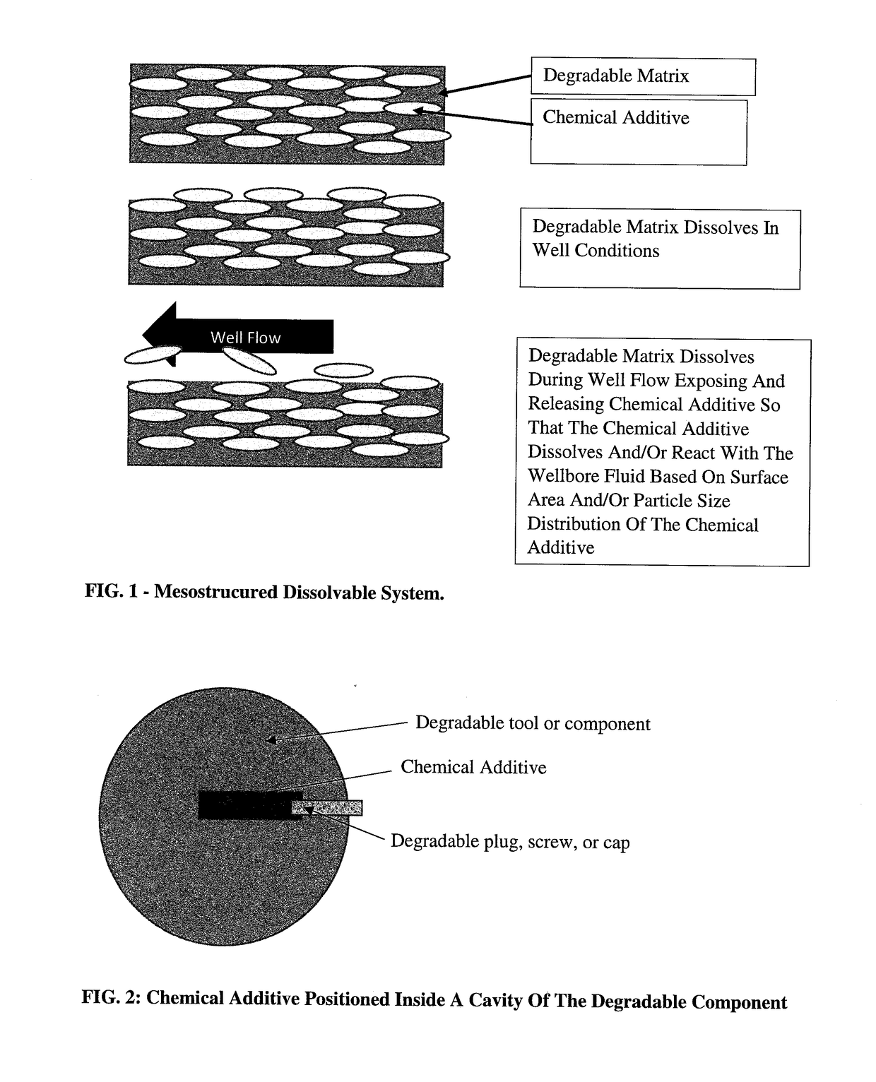
The patent describes a way to control the degradation of a component in a tool used in oil and gas drilling. This is done by adding chemicals like salts or acids to the degradable component, which can be released as the component breaks down. The chemicals help to prevent the buildup of magnesium hydroxide and maintain the degradation rate of the component, even if there is poor fluid circulation around it. Another aspect of the patent is the use of a tracer element that can be added to the tool or degradable component. When the component breaks down, the tracer element generates a detectable signal that can be easily detected.

Problems solved by technology

These long laterals, deep wells, and high deviations increase costs and difficulties for intervention activities (such as drill-out or retrieval of plugs) and often exceed the distances where coiled tubing intervention services can be effectively used.
One of the difficulties in using components formed of degradable and / or dissolvable materials is that sometimes such components have been known to not degrade or not properly degrade.
Changes in pH, such as a pH increase due to the production of hydroxides, can affect the formation and inhibit the effectiveness of gel-breakers or acidizing treatments.
However, these chemical pills and gel-breakers are not effective if a degradable component has not degraded or has not properly degraded, thereby interfering with the proper flow or the flow past the degradable component.
Components formed of degradable and / or dissolvable materials can normally be easily drilled out or otherwise removed (if accessible), but at added cost, which decreases the value of using the degradable.

Method used


Image

  • Method of Assuring Dissolution of Degradable Tools
  • Method of Assuring Dissolution of Degradable Tools
  • Method of Assuring Dissolution of Degradable Tools

Examples


example 1

Soluble Mesostructured Degradable Tracer

[0225]A mesostrucured tracer / degradable system is provided wherein the degradable component is soluble in the well (aqueous) fluid, thereby exposing the tracer element to the well flow conditions. The tracer element includes stable isotopes not common in the well formation, and which the tracer element is normally in the form of oxide or intermetallic particles. The tracer element is released from the degradable component as the degradable component degrades. The degradable component can be formed of a polymeric and / or metallic material. The released tracer elements can be analyzed on-site by testing the fluid flow or back flow of fluid from the well or by sending a sample of the fluid containing the tracer elements to an outside lab, typically a lab that uses high resolution GC-MS techniques; however, this is not required.

[0226]For example, the tracer element can be formed from rare earth oxide nanoparticles (CeO, Ge2O3, Sm2O3, Nd2O3, etc.) t...

example 2

Tracer Incorporation

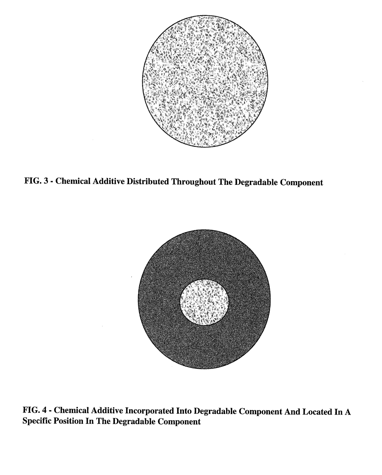
[0229]The system as set forth in Example 1 releases tracer elements continuously during degradation / dissolution of the degradable component, and requires knowledge of the total flow of fluid past the degradable component and a recovery of a known percentage of the tracer element to assess the complete or desired amount of removal of the degradable component in the well. Such information can be facilitated by adding the tracer element at a select depth in the degradable component (such as the center of a degradable component [e.g., frac ball, etc.]). In such an arrangement, the tracer element can be added to the degradable component in a more concentrated form; however, this is not required if the release is detectable at lower concentrations. The insertion of the tracer element can be incorporated in the interior of the degradable component by various processes, for example, by drilling a hole or machining a cavity into the degradable component, placing the trace...

example 3

[0230]A dissolvable metal frac ball having outer dimensions of 3.750 inches+ / −0.003 inches is machined to form a hollow core having dimensions of 0.75 inch×2.5 inch. The hollow core thus constitutes less than 15 vol. % of the frac ball. The upper 1 inch of the cavity is machined with female NPT threads to accept a plug. One or more microRFID tags (e.g., 1-5 microRFID tags) having dimensions to fit into the hollow core (e.g., 0.6″ dia×0.1″) are coated with a coating to protect the one or more microRFID tags and / or provide buoyancy to the one or more microRFID tags so that the microRFID tags can float in the flowing water after being released form the degradable component. The coating is typically a non-degradable coating in the well fluid. The coating thickness is generally at least about 0.005 inches and typically about 0.01 inches to 0.1 inches (and all values and ranges therebetween). One non-limiting coating is a polyurethane coating. The coating can optionally can include about ...


PUM

PropertyMeasurementUnit
hydrostatic pressureaaaaaaaaaa
pressureaaaaaaaaaa
temperaturesaaaaaaaaaa

Abstract

The use of degradable components has become a more common practice in subterranean operations for such applications as temporarily isolating zones or diverting flow. A major concern of operators in using degradable tools is the ability to ensure that the tool has completely degraded and is no longer blocking or obstructing flow. This issue can be resolved through the use of degradable components that include one or more chemical additives that are released upon the partial or full dissolution of the degradable component, and which can be used to facilitate in the dissolution of the degradable component. The degradable component can optionally include tracer elements that are released upon the partial or full dissolution of the degradable component, and which can be detected at the surface to ensure the desired degradation or removal of the degradable component as well as hydraulic access to that stage.

Description

[0001]The present invention claims priority on U.S. Provisional Patent Application No. 62 / 599,183 filed Dec. 15, 2017, which is incorporated herein by reference.[0002]The present invention is a continuation-in-part of U.S. patent application Ser. No. 15 / 701,701 filed Sep. 12, 2017, which in turn claims priority to U.S. Provisional Application No. 62 / 398,867 filed Sep. 23, 2016, which are incorporated herein by reference.[0003]The present invention relates to the enhanced use of degradable or dissolving tools and devices used in subterranean operations such as drilling, completion, and stimulation operations used in enhanced geothermal, oil and gas, and waste disposal (injection) operations. In particular, the invention relates to degradable components that include one or more materials to control local salinity and / or pH upon the partial or full dissolution of the degradable component, and more particularly to degradable components that include one or more materials that are time re...

Claims


Application Information

Patent Timeline
Patent Type & Authority Applications(United States)
IPC IPC(8): E21B47/10E21B29/00G01N33/24
CPCE21B47/1015E21B29/00G01N33/24E21B33/12E21B34/063E21B29/02E21B47/11
Inventor SHERMAN, ANDREWDOUD, BRIAN
Owner TERVES
Learn More