
Device for analyzing a product to be analyzed located in a product space

a technology for analyzing devices and products, applied in the direction of material analysis, material analysis, instruments, etc., can solve the problems of sensor “blindness”, sensor integration of prisms or even plates in process probes, and contamination on the surface is a certain problem, so as to ensure rapid material exchange on the surface, facilitate cleaning, and ensure good flow

Active Publication Date: 2018-10-25
ENDRESSHAUSER CONDUCTA GMBHCO
View PDF19 Cites 7 Cited by
  • Summary
  • Abstract
  • Description
  • Claims
  • Application Information

AI Technical Summary

Benefits of technology

The invention is a process analytics probe with an ATR element integrated into the probe body in a favorable manner for both optical and fluidic considerations. The integration of the ATR element allows for easy cleaning and ensures a rapid material exchange on the surface. The analysis device is suitable for various industrial applications, such as chemical and pharmaceutical industries, food industry, petrochemical and oil industry, and biotechnology. The invention enhances process analytics, leading to higher plant efficiencies and consistently higher product qualities. The ATR element can be designed as a hollow cylinder or sphere, and a spiral light propagation can be achieved to further extend the light path. The invention also includes the possibility of using a wedge-shaped notch or lattice structures for the coupling-in and coupling-out of light.

Problems solved by technology

In general, contaminants on the surface is a certain problem in ATR spectroscopy, irrespective of the stated spectral region.
Coverings on the surface result in the sensor becoming “blind”.
A particular challenge is the integration of such prisms or even plates in process probes.
In the case of an ATR element at the tip, the number of reflections and thus the sensitivity is, however, limited.
Cleaning the edges and projections with cleaning liquids, with hot steam or mechanical means is then accordingly complicated.

Method used


Image

  • Device for analyzing a product to be analyzed located in a product space
  • Device for analyzing a product to be analyzed located in a product space
  • Device for analyzing a product to be analyzed located in a product space

Examples


Embodiment Construction

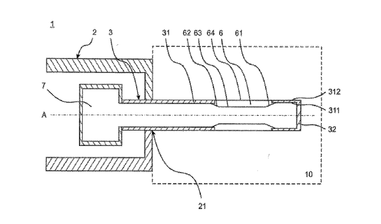
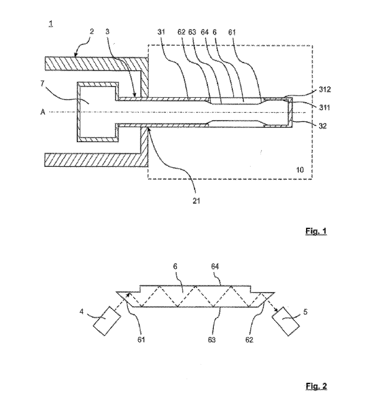
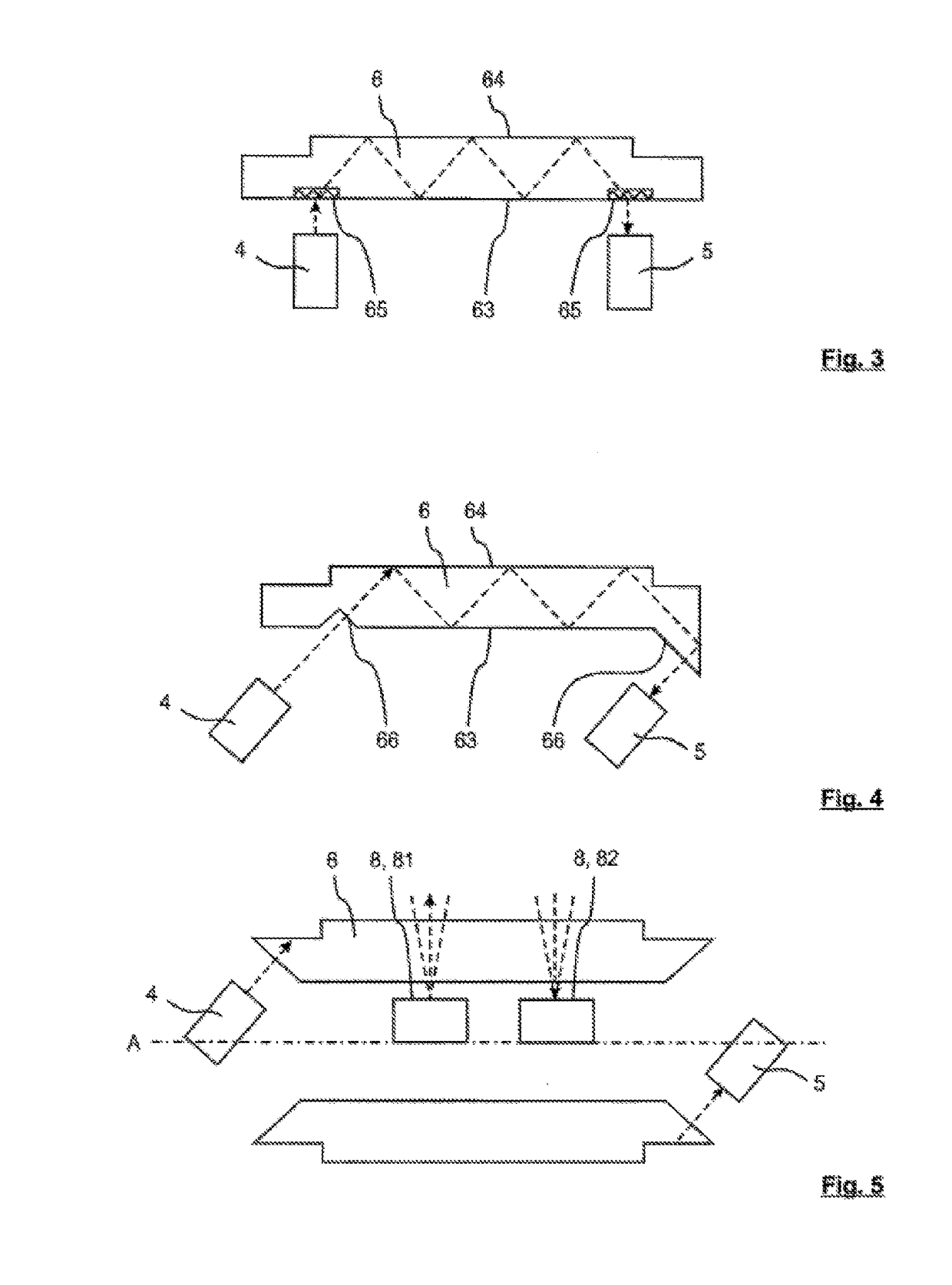
[0053]FIG. 1 shows schematically a longitudinal section of an analysis device 1 according to an exemplary embodiment of the invention as process probe with cylindrical ATR element 6. The analysis device 1 has a probe housing 2 having an opening 21 in which a probe body 3 is positioned. Fitted in the circumferential wall of the probe body 31 is an ATR element 6 as measurement window. In this embodiment, the ATR element 6 is a hollow cylinder having an entrance region 61 and an exit region 62 for the measurement radiation. The inner side 63 and the outer side 64 of the ATR element 6 guide the measurement radiation by total reflection from the entrance region 61 to the exit region 62. The outer side 64 of the ATR element 6 aligns with the outer side of the circumferential wall 312 of the probe body 3. Owing to a tapered realization of the entrance region 61 and of an exit region 62 of the ATR element 6, the inner side 63 is somewhat elevated with respect to the inner side of the circum...


PUM

PropertyMeasurementUnit
wavelengthsaaaaaaaaaa
thicknessesaaaaaaaaaa
thicknessaaaaaaaaaa

Abstract

A device for analysing a product to be analysed which is located in a product space having a probe body arranged in a probe housing and having a peripheral wall, and at least one radiation source and at least one optical receiver. At least one measurement window in the probe body has an entry region and an exit region for measurement radiation. An evaluation unit is also provided. The probe body can be brought into a measurement position, in which at least one part of the probe body in which the measurement window is located penetrates through an opening of the probe housing into the product space for the analysis. In addition, the probe body can be brought into a retracted position, in which the probe body is still located at least partially in the region of the opening of the probe housing and thus covers the opening.

Description

[0001]This nonprovisional application is a continuation of International Application No. PCT / EP2016 / 082520, which was filed on Dec. 23, 2016, and which claims priority to German Patent Application No. 10 2015 122 995.1, which was filed in Germany on Dec. 30, 2015, and which are both herein incorporated by reference.BACKGROUND OF THE INVENTIONField of the Invention[0002]The present invention relates to a device for analyzing a product to be analyzed that is located in a product space.Description of the Background Art[0003]To increase the flexibility and efficiency of industrial production processes, a comprehensive understanding of processes is necessary. Sensors providing information about material compositions, process parameters, reaction processes and product qualities are required.[0004]Distinct advantages are provided here by optical spectroscopic sensors, which function without media contact. The most commonly used technique is spectroscopy in the near-infrared region (NIR) wi...

Claims


Application Information

Patent Timeline
Patent Type & Authority Applications(United States)
IPC IPC(8): G01N21/85G01N21/3577G01N21/552
CPCG01N21/8507G01N21/3577G01N21/552G01N2021/8528G01N21/65G01N21/53
Inventor MANNHARDT, JOACHIMLAMBRECHT, ARMINSULZ, GERD
Owner ENDRESSHAUSER CONDUCTA GMBHCO
Learn More