EUV photopatterning and selective deposition for negative pattern mask

Inactive Publication Date: 2018-10-25
LAM RES CORP
View PDF6 Cites 14 Cited by
  • Summary
  • Abstract
  • Description
  • Claims
  • Application Information

AI Technical Summary

Benefits of technology

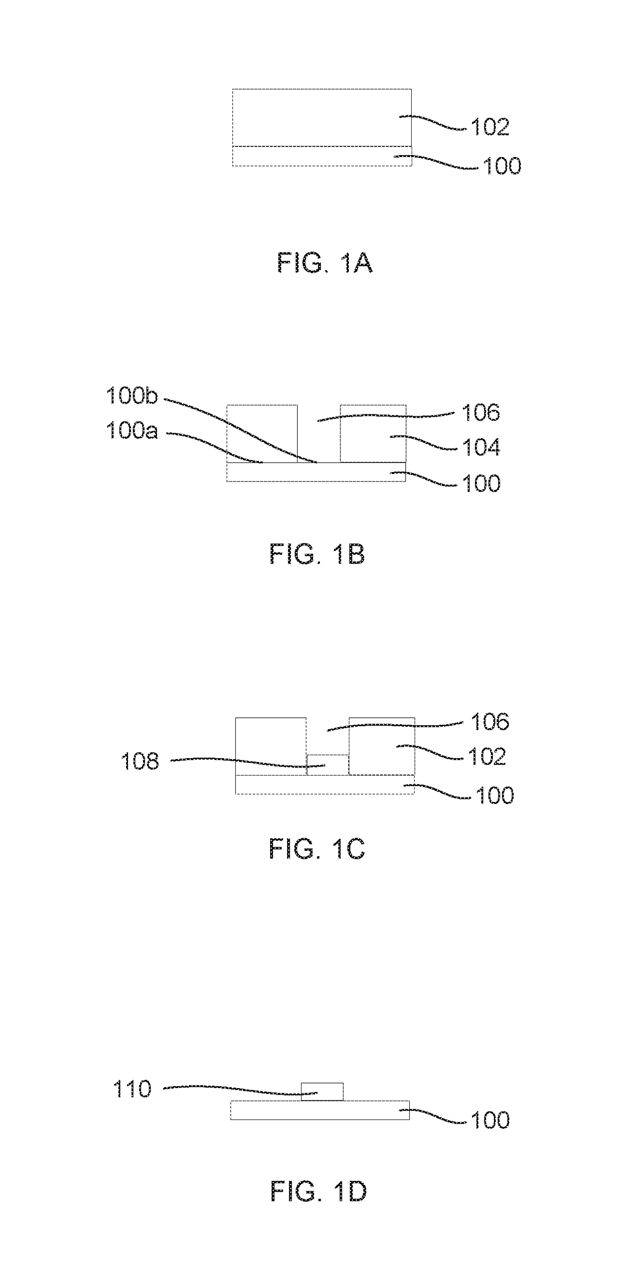
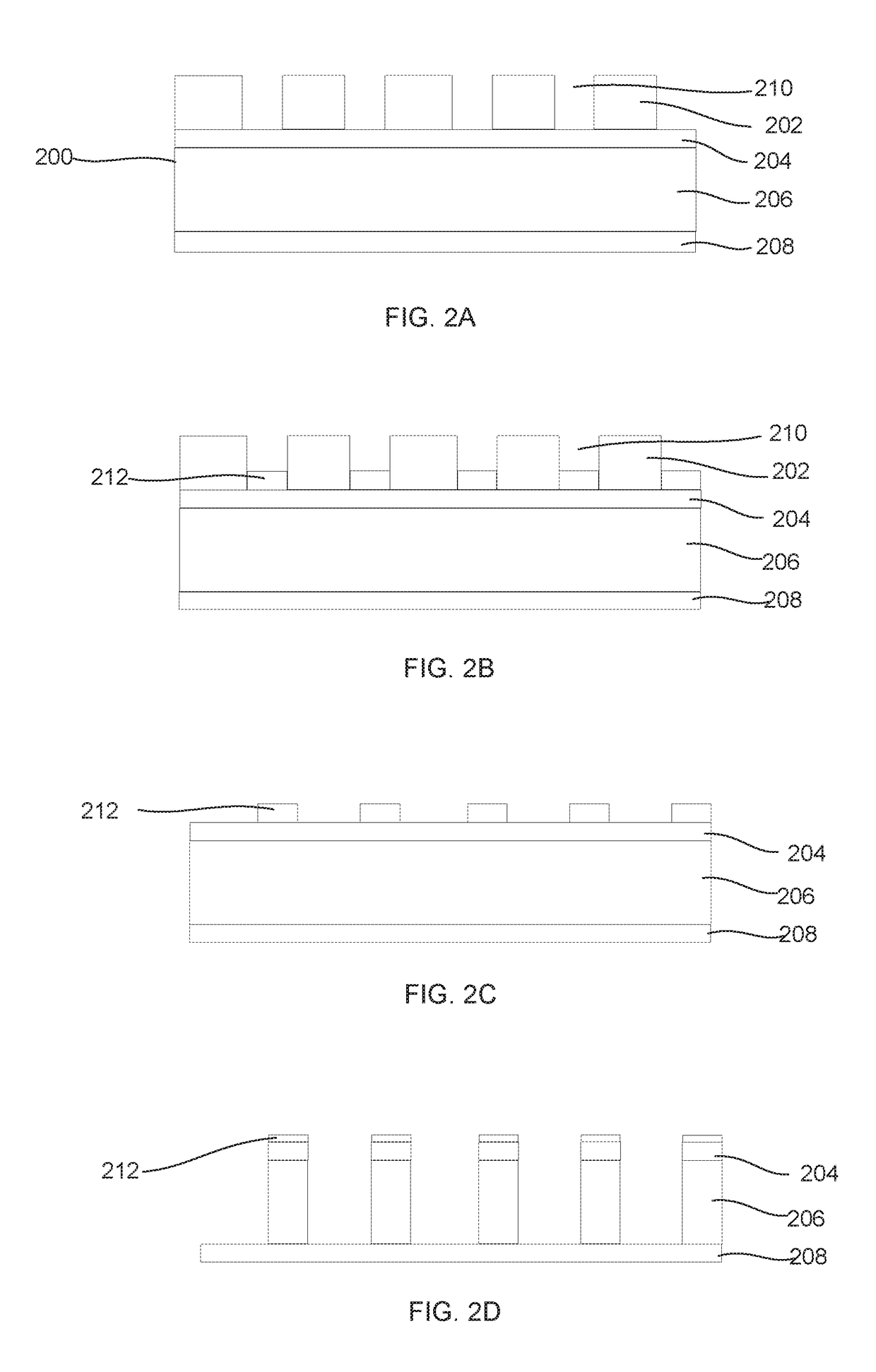
[0006]This disclosure provides method and apparatus for using a selective deposition process to deposit a metal oxide or metal nitride thin film in a feature defined in an EUV resist to prepare a negative image for patterning. This method to produce the “negative” image does not i

Problems solved by technology

Thin CARs, however, dictate process window and can increase complexity by necessitating the use of additional layers to support multi-step pattern transfer.
Etch back steps have limited selectivity that can result in the gapfill feature being shorter than optimal for a mask.
For example, the selective deposition may be conducted by a non-plasma thermal ALD process, since the plasma may damage the resist and plasma processes are susceptible to re-deposition, e.g., on the resist.
Plasma processing has been found to be disfavored since the plasm

Method used


Image

  • EUV photopatterning and selective deposition for negative pattern mask
  • EUV photopatterning and selective deposition for negative pattern mask
  • EUV photopatterning and selective deposition for negative pattern mask

Examples


Embodiment Construction

[0019]Reference will now be made in detail to specific embodiments of the disclosure. Examples of the specific embodiments are illustrated in the accompanying drawings. While the disclosure will be described in conjunction with these specific embodiments, it will be understood that it is not intended to limit the disclosure to such specific embodiments. On the contrary, it is intended to cover alternatives, modifications, and equivalents as may be included within the spirit and scope of the disclosure. In the following description, numerous specific details are set forth in order to provide a thorough understanding of the present disclosure. The present disclosure may be practiced without some or all of these specific details. In other instances, well known process operations have not been described in detail so as to not unnecessarily obscure the present disclosure.

INTRODUCTION

[0020]Extreme ultraviolet (EUV) lithography can extend lithography technology beyond its current resolutio...


PUM

PropertyMeasurementUnit
Widthaaaaaaaaaa
Electrical resistanceaaaaaaaaaa
Semiconductor propertiesaaaaaaaaaa

Abstract

Process and apparatus for forming a negative patterning mask in the context of EUV patterning uses a selective deposition process to deposit a metal oxide or metal nitride thin film in a feature defined in an EUV resist to prepare a negative image for patterning. The method to produce the “negative” image does not involve an etch back step and therefore accommodates the small resist budget. The material forming the “negative” image is significantly more etch resistant than resist which eliminates the need for an additional hard mask transfer layer.

Description

FIELD OF THE DISCLOSURE[0001]This disclosure relates generally to the field of semiconductor processing. In particular aspects, the disclosure is directed to process and apparatus for using selective deposition to form a negative patterning mask in the context of EUV patterning.BACKGROUND[0002]Patterning of thin films in semiconductor processing is often a critical step in the fabrication of semiconductors. Patterning involves lithography. In conventional photolithography, such as 193 nm photolithography, patterns are printed by emitting photons from a photon source onto a mask and printing the pattern onto a photosensitive photoresist, thereby causing a chemical reaction in the photoresist that, after development, removes certain portions of the photoresist to form the pattern.[0003]Advanced technology nodes (as defined by the International Technology Roadmap for Semiconductors) include nodes 22 nm, 16 nm, and beyond. In the 16 nm node, for example, the width of a typical via or li...

Claims


Application Information

Patent Timeline
IPC IPC(8): H01L21/027H01L21/02C23C16/40C23C16/455C23C16/56C23C16/44C23C16/52
CPCH01L21/0274H01L21/0228H01L21/02164C23C16/405C23C16/52C23C16/402C23C16/56C23C16/4408C23C16/45544C23C16/04C23C16/34C23C16/45525H01L21/02181H01L21/02186H01L21/02211H01L21/02219H01L21/0332H01L21/0337H01L21/32H01L21/288
Inventor SMITH, DAVID CHARLESMAHOROWALA, ARPAN
Owner LAM RES CORP
Why Eureka
Try Eureka