Stacked output structure of capacitive power supply for welding equipment

a capacitive power supply and output structure technology, applied in the direction of high current circuit adaptation, manufacturing tools, non-printed electric components association, etc., can solve the problems of reducing the energy density in unit time cannot be clearly improved when discharging, and the need for more contacts and a longer power bus for conduction, so as to improve the output ratio of capacitive power supply, reduce impedance and inductive reactance, the effect of flexible arrangemen

Inactive Publication Date: 2018-10-25
BOSJOB
View PDF0 Cites 1 Cited by
  • Summary
  • Abstract
  • Description
  • Claims
  • Application Information

AI Technical Summary

Benefits of technology

[0015]Advantages of the embodiments of the present disclosure include the following. Compared with the prior art, the stacked output structure of the capacitive power supply provided by the present disclosure can greatly reduce the impedance and inductive reactance when outputting the power, and improve the output ratio of the capacitive power supply. Besides, the stacked output structure allows a more flexible arrangement and can be conveniently connected with other components, such as the control board, etc. Thus, the stacked output structure is practical and convenient and has great market competitiveness.

Problems solved by technology

The disadvantage of the traditional capacitive power supply are as follows: the greater the capacity of the electrolytic capacitor is, the larger the impedance and the inductive reactance in the capacitor; the poorer high-frequency dynamic response resulting in a reduced discharging speed, so that the energy density in unit time cannot be obviously improved when discharging.
However, more parallelly connected capacitors mean that more contacts and a longer power bus are needed for conduction.
This is very unfavorable for the applications requiring high instantaneous current output.
Thus, cables or additional power buses have to be used for bridge connection to connect and introduce the positive and negative output ends to the output ends of the equipment, which, however, increases the output impedance.

Method used


Image

  • Stacked output structure of capacitive power supply for welding equipment
  • Stacked output structure of capacitive power supply for welding equipment
  • Stacked output structure of capacitive power supply for welding equipment

Examples


Embodiment Construction

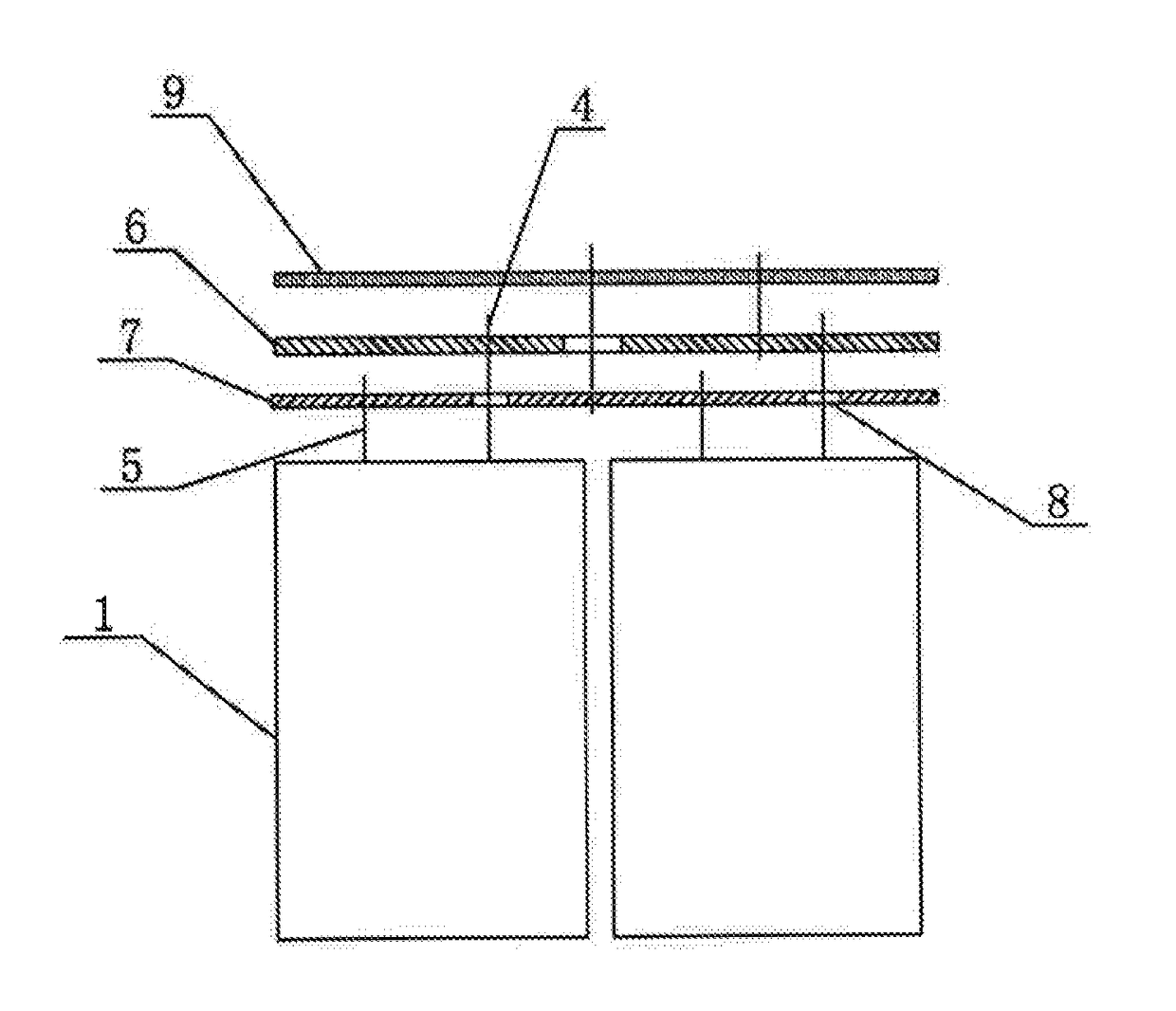
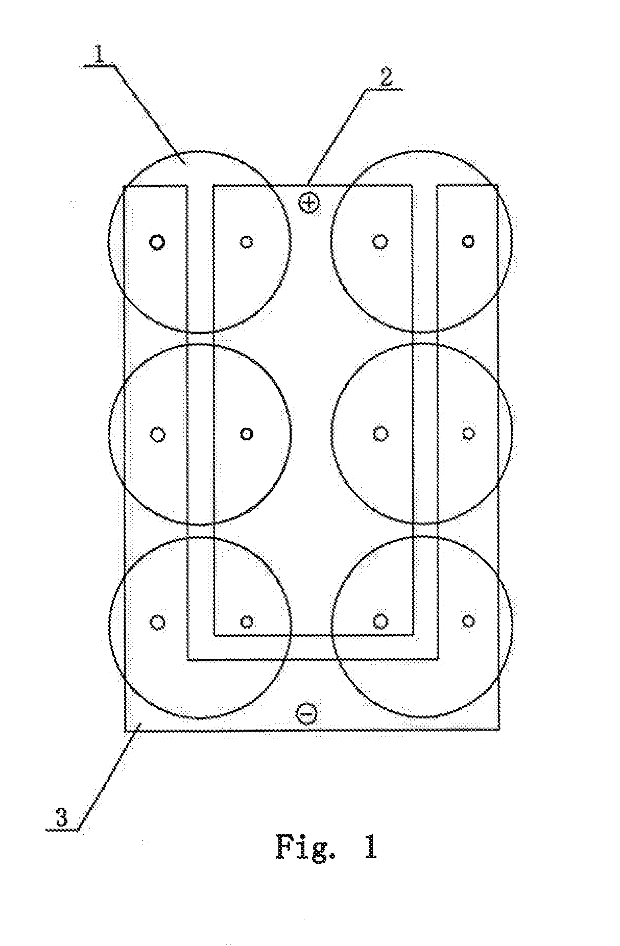
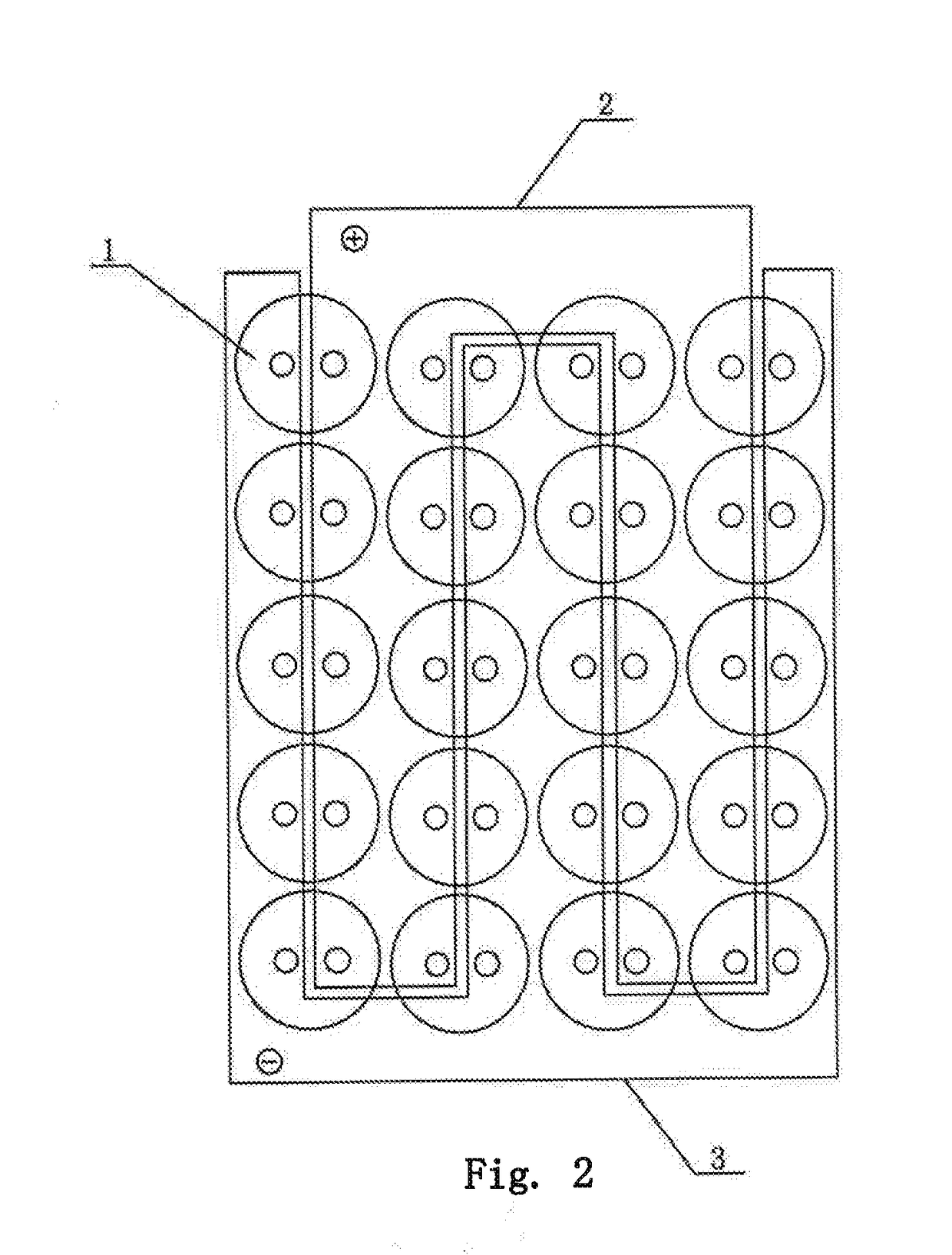
[0024]Referring to FIG. 3, an embodiment of the present disclosure provides a stacked output structure of a capacitive power supply with two PCB (printed circuit board) bus plates. The embodiment includes a plurality of capacitors 1 to be connected in parallel; two electrodes of each capacitor are respectively provided with a pin upwards, and each capacitor has two pins, including a long pin 4 and a short pin 5. In the embodiment, the long pin 4 is connected with a positive electrode of the capacitor 1; and the short pin 5 is connected with a negative electrode of the capacitor 1. Two PCB bus plates in stack are arranged above the capacitor 1, wherein a lower negative PCB bus plate 7 (as shown in cross sectional view) is connected with the short pin 5 to converge the current from the negative electrode; a pass-through hole 8 is arranged, at a position corresponds to the long pin 4, on the negative PCB bus plate 7; the long pin 4 is connected with an upper positive PCB bus plate 6 lo...


PUM

PropertyMeasurementUnit
heightaaaaaaaaaa
conductiveaaaaaaaaaa
polarityaaaaaaaaaa

Abstract

A stacked output structure of a capacitive power supply for welding equipment, having a plurality of capacitors to be connected in parallel, two electrodes of each capacitor are respectively provided with a pin including a long pin and a short pin; at least two PCB bus plates placed in stack are provided above the capacitor is provided. A lower PCB bus plate is connected with the short pin; and a pass-through hole is provided, at a position corresponds to the long pin, on the lower PCB bus plate. The long pin passes through the pass-through hole in the lower PCB bus plate and is connected with an upper PCB bus plate. There is a gap between the long pin and an inner wall of the pass-through hole.

Description

FIELD OF INVENTION[0001]The present disclosure relates to a power supply of welding equipment, and in particular, to a stacked output structure of a capacitive power supply for welding equipment.BACKGROUND OF INVENTION[0002]There are several conventional power supplies available for welding equipment, which are simply classified as a transformer type, an inverter type, a storage capacitor type, etc. The storage capacitor power supply has the advantages of short welding time, high energy density in unit time, etc., and is widely applied in welding equipment, such as an energy storage type stud welding machine, a spot welding machine, a cold patching machine, etc.[0003]A traditional capacitive power supply adopts a screw type large electrolytic capacitor which conducts large-current discharge cooperating with a copper bar, an aluminum bar or a cable, with a peak current at the moment of discharging up to thousands or even tens of thousands of amperes. The disadvantage of the tradition...

Claims


Application Information

Patent Timeline
Patent Type & Authority Applications(United States)
IPC IPC(8): H05K1/18H05K1/14H05K1/02B23K9/10
CPCH05K1/18H05K1/144H05K1/0263B23K9/1006H05K2201/09227H05K2201/10015H05K2201/10166H05K2201/10522H05K2201/10189H05K2201/10303H05K2201/10333H05K2201/10651H05K2201/10901B23K9/007B23K9/105B23K9/20B23K11/11B23K11/248H05K2201/10272H02G5/00
Inventor WENG, LIANG-HUANWENG, MIN-HSIANG
Owner BOSJOB
Why Eureka
Try Eureka