Methods and systems for rebalancing electrolytes for a redox flow battery system

a flow battery and electrolyte technology, applied in the direction of electrolyte stream management, regenerative fuel cells, fuel cells, etc., can solve the problems of increasing the number of catalysts needed, the typical rebalancing reactor may exhibit less favorable reaction kinetics, and the need for significantly more catalysts to be utilized. , to achieve the effect of increasing efficiency and cost-effectiveness

Pending Publication Date: 2018-11-01
ESS TECHNOLOGY
View PDF3 Cites 25 Cited by
  • Summary
  • Abstract
  • Description
  • Claims
  • Application Information

AI Technical Summary

Benefits of technology

[0005]One system that at least partially addresses the issues identified above, includes a rebalancing reactor for a redox flow battery system, including a first side through which hydrogen gas is flowed, a second side through which electrolyte from the redox flow battery system is flowed, and a porous layer separating and fluidly coupled to the first side and the second side. The hydrogen gas and the electrolyte are fluidly contacted at a surface of the porous layer. Furthermore, in one example, a pressure drop across the second side may be less than a pressure drop across the porous layer. In this way, rebalancing of electrolyte charges in a redox flow battery system may be performed with increased efficiency and cost effectiveness as compared to packed bed and other conventional designs.

Problems solved by technology

Typical packed bed-type rebalancing reactors may exhibit less favorable reaction kinetics primarily because the rebalancing reactor system is in two-phase flow.
As a result, mass transport losses in the packed bed-type rebalancing reactor systems can be higher, requiring significantly more catalyst to be utilized.
Conventionally, a general approach to compensating for mass transport limitations has been to oversize the rebalancing reactors; however, oversizing the rebalancing reactors can be costly, and may further suffer from poor catalyst utilization.

Method used


Image

  • Methods and systems for rebalancing electrolytes for a redox flow battery system
  • Methods and systems for rebalancing electrolytes for a redox flow battery system
  • Methods and systems for rebalancing electrolytes for a redox flow battery system

Examples


Embodiment Construction

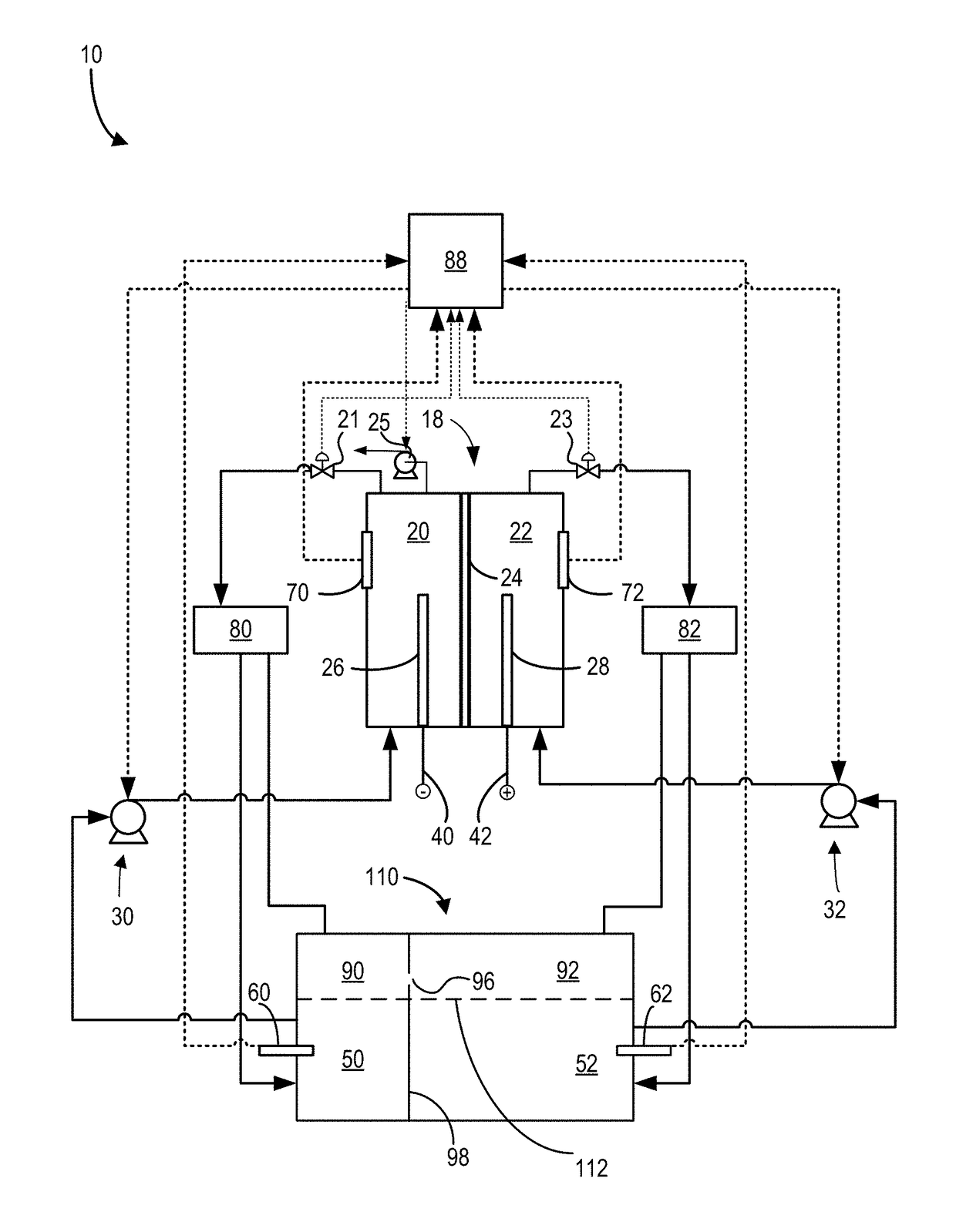
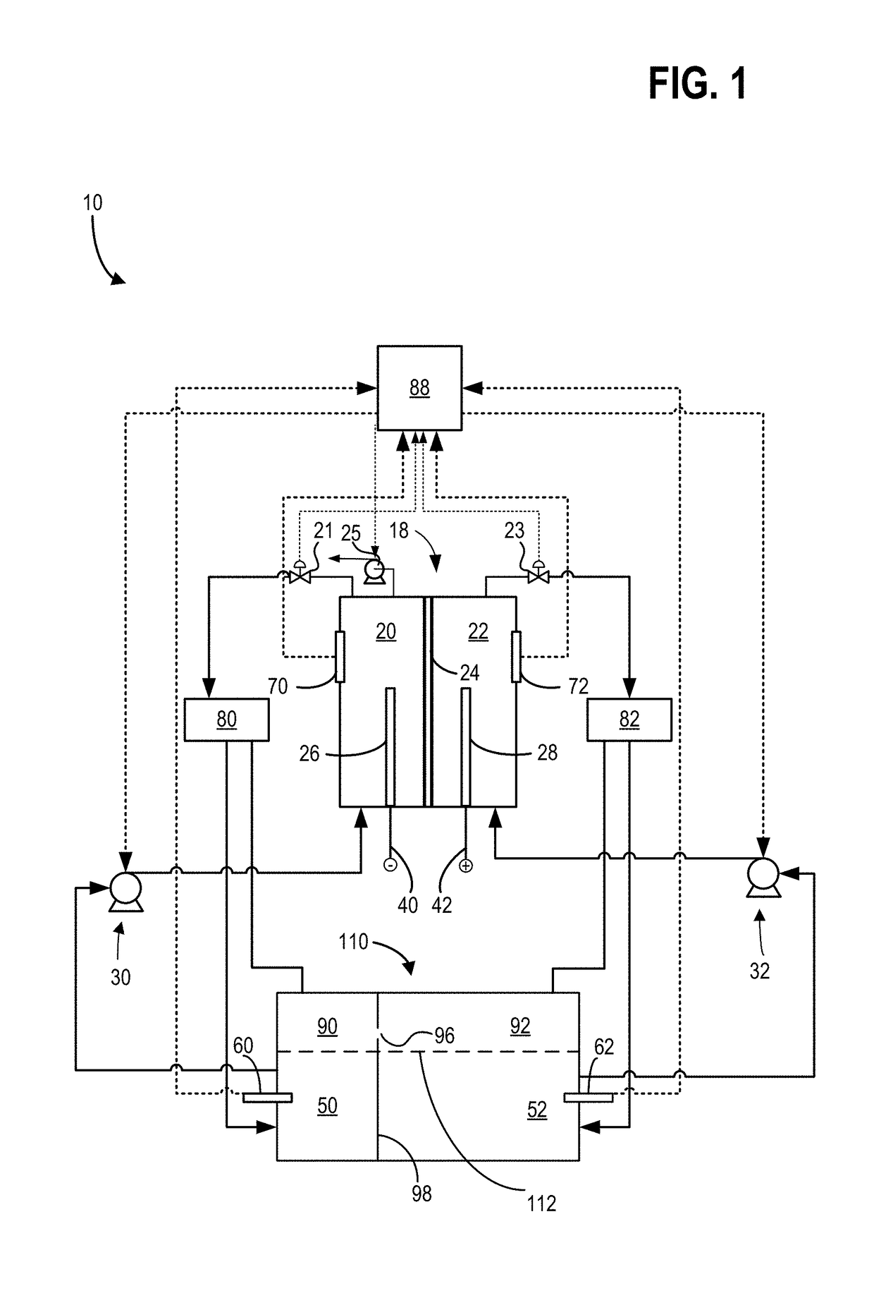
[0014]Hybrid redox flow batteries are redox flow batteries that are characterized by the deposit of one or more of the electro-active materials as a solid layer on an electrode. Hybrid redox flow batteries may, for instance, include a chemical that plates via an electrochemical reaction as a solid on a substrate throughout the battery charge process. During battery discharge, the plated species may ionize via an electrochemical reaction, becoming soluble in the electrolyte. In hybrid battery systems, the charge capacity (e.g., amount of energy stored) of the redox battery may be limited by the amount of metal plated during battery charge and may accordingly depend on the efficiency of the plating system as well as the available volume and surface area available for plating.

[0015]In a redox flow battery system the negative electrode 26 may be referred to as the plating electrode and the positive electrode 28 may be referred to as the redox electrode. The negative electrolyte within t...


PUM

PropertyMeasurementUnit
pressureaaaaaaaaaa
pressure dropaaaaaaaaaa
electric currentaaaaaaaaaa

Abstract

A rebalancing reactor for a redox flow battery system may include a first side through which hydrogen gas is flowed, a second side through which electrolyte from the redox flow battery system is flowed, and a porous layer separating and fluidly coupled to the first side and the second side, wherein, the hydrogen gas and the electrolyte are fluidly contacted at a surface of the porous layer, and a pressure drop across the second side is less than a pressure drop across the porous layer. In this way, rebalancing of electrolyte charges in a redox flow battery system may be performed with increased efficiency and cost effectiveness as compared to conventional rebalancing reactors.

Description

CROSS REFERENCE TO RELATED APPLICATIONS[0001]The present application claims priority to U.S. Provisional Application No. 62 / 491,966, entitled “Methods and System for a Rebalancing Electrolytes for a Redox Flow Battery System”, and filed on Apr. 28, 2017. The entire contents of the above-listed application are hereby incorporated by reference for all purposes.ACKNOWLEDGMENT OF GOVERNMENT SUPPORT[0002]This invention was made with government support under contract No. DEAR0000261 awarded by the DOE, Office of ARPA-E. The government has certain rights in the invention.FIELD[0003]The present description relates generally to rebalancing reactors for flow battery systems.BACKGROUND AND SUMMARY[0004]Typical packed bed-type rebalancing reactors may exhibit less favorable reaction kinetics primarily because the rebalancing reactor system is in two-phase flow. As a result, mass transport losses in the packed bed-type rebalancing reactor systems can be higher, requiring significantly more catal...

Claims


Application Information

Patent Timeline
Patent Type & Authority Applications(United States)
IPC IPC(8): H01M8/0662H01M8/18H01M8/2455H01M8/04276
CPCH01M8/0687H01M8/188H01M8/2455H01M8/04276H01M8/04186Y02E60/50
Inventor EVANS, CRAIG E.
Owner ESS TECHNOLOGY
Why Eureka
Try Eureka