Electronic apparatus

Active Publication Date: 2018-11-01
SONY CORP
View PDF9 Cites 4 Cited by
  • Summary
  • Abstract
  • Description
  • Claims
  • Application Information

AI Technical Summary

Benefits of technology

The patent technology can effectively lower the temperature inside electronic devices and prevent them from getting overheated. This can improve the performance and reliability of the devices.

Problems solved by technology

However, there is a limit temperature up to which each of electronic members disposed inside can be used, and it is necessary to provide a total heat design including a heat storage material so as not to exceed such a limit temperature.

Method used


Image

  • Electronic apparatus
  • Electronic apparatus
  • Electronic apparatus

Examples


first embodiment

1. FIRST EMBODIMENT

[0023][1-1. Configuration of Electronic Apparatus]

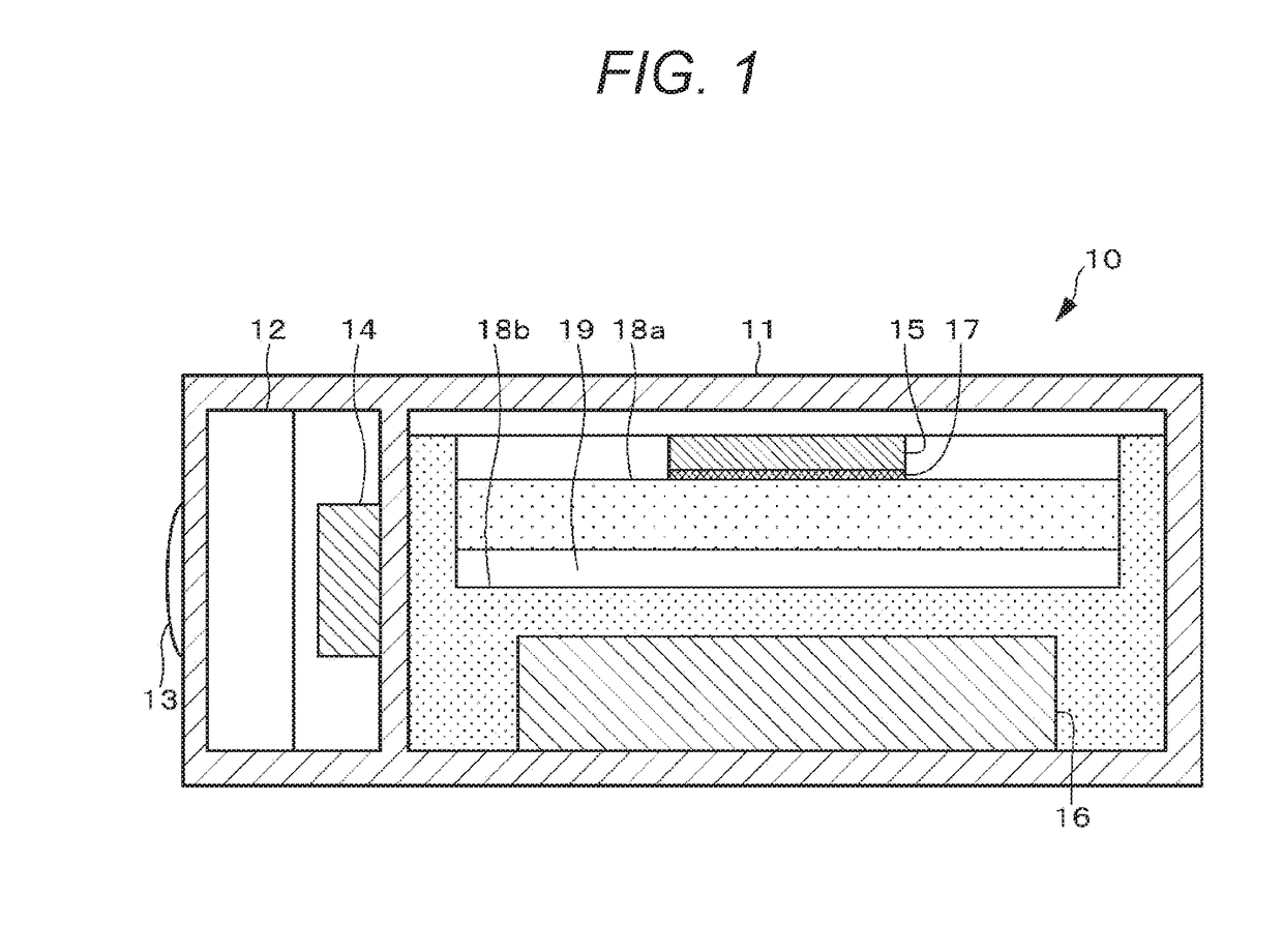
[0024]First, an exemplary configuration of an imaging device that is an electronic apparatus 10 according to a first embodiment will be described. FIG. 1 is a schematic cross-sectional plan view illustrating a configuration of an electronic apparatus 10.

[0025]The electronic apparatus 10 includes a housing 11, a lens barrel 12, an imaging element 14, a control circuit 15, a battery 16, a heat dissipation sheet 17, a first heat storage material 18a, and a second heat storage material 18b.

[0026]The housing 11 includes a synthetic resin such as plastic, a metal, or the like, and constitutes an outer package of the electronic apparatus 10. The lens barrel 12, imaging element 14, control circuit 15, battery 16, first heat storage material 18a, and second heat storage material 18b are provided inside the housing 11.

[0027]The inside of the lens barrel 12 is provided with a drive mechanism, an iris mechanism, a shutter mec...

second embodiment

2. SECOND EMBODIMENT

[0069][2-1. Configuration of Electronic Apparatus]

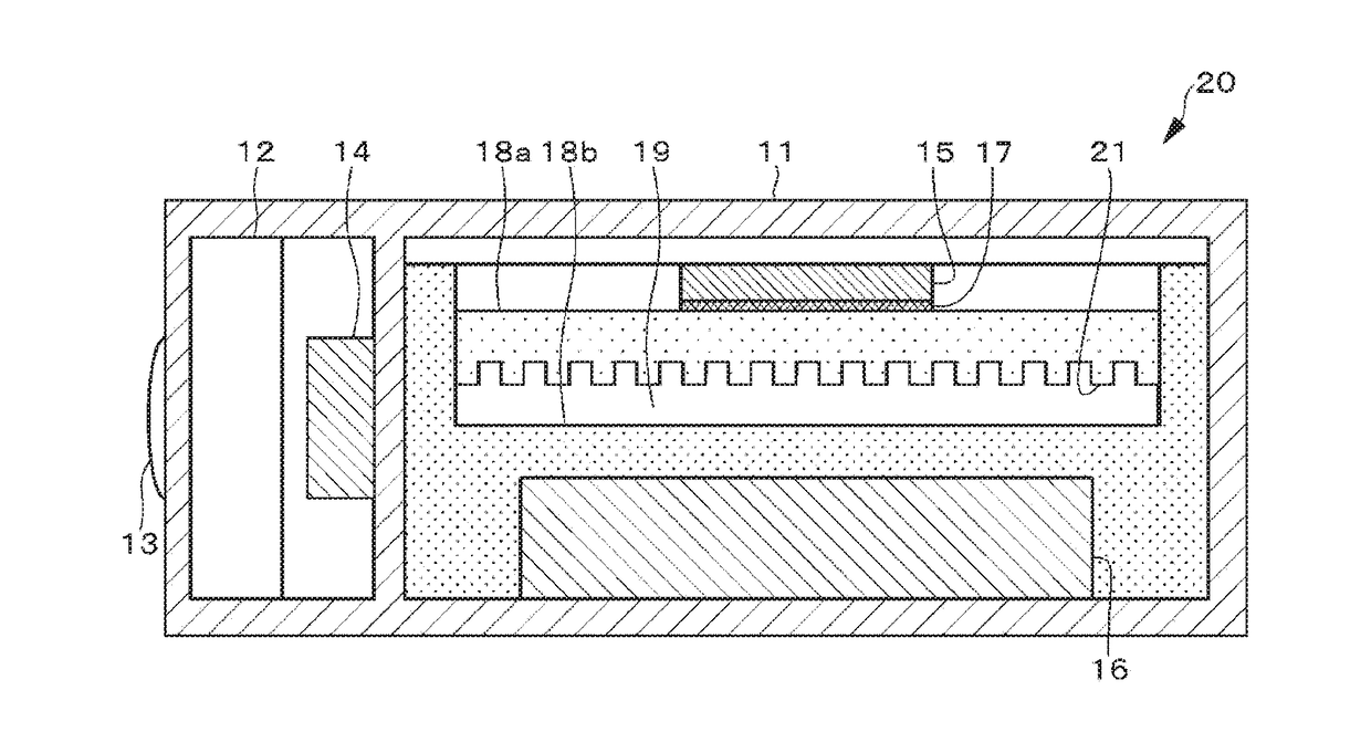
[0070]An exemplary configuration of an electronic apparatus 20 according to a second embodiment of the present technology will be described with reference to FIG. 5. Meanwhile, since a configuration of the electronic apparatus 20 other than a first heat storage material 18a is similar to that of a first embodiment, the description thereof will be omitted. In the second embodiment also, the description will be provided by exemplifying an imaging device as the electronic apparatus 20 in a manner similar to the first embodiment.

[0071]A plurality of uneven surfaces 21 is formed on an entire portion of a surface of the first heat storage material 18a located on an opposite side of a control circuit 15 side, namely, the surface facing a gap 19. The uneven surface 21 is adopted to increase an surface area of the surface of the first heat storage material 18a on the gap 19 side. The uneven surface 21 is an example of a “s...

third embodiment

3. THIRD EMBODIMENT

[0072][3-1. Configuration of Electronic Apparatus]

[0073]An exemplary configuration of an electronic apparatus 30 according to a third embodiment of the present technology will be described with reference to FIG. 6. Since the configuration of the electronic apparatus 30 other than a heat storage material 31 and a gap 32 is similar to that of a first embodiment, the description thereof will be omitted. In the third embodiment also, the description will be provided by exemplifying an imaging device as the electronic apparatus 30 in a manner similar to the first embodiment.

[0074]In the third embodiment, the heat storage material 31 is provided in manner thermally connected to a control circuit 15 via a heat dissipation sheet 17. On the other hand, no heat storage material is provided in a manner contacting a battery 16, and the heat storage material 31 does not also contact the battery 16, and a gap 32 is formed between the heat storage material 31 and the battery 16....


PUM


Abstract

Provided is an electronic apparatus including: a housing; a control circuit provided inside the housing; a battery provided inside the housing; a heat storage material provided between the control circuit and the battery inside the housing; and a gap provided between the control circuit and the battery.

Description

TECHNICAL FIELD[0001]The present technology relates to an electronic apparatus.BACKGROUND ART[0002]In an electronic apparatus such as a digital camera, miniaturization is demanded while power consumption is increased due to achievement of high performance, and it is a serious problem to suppress temperature rise caused by heat generation of an internal component. Excessive temperature rise of an electronic component may damage reliability and a function of the component and may shorten the life of an apparatus. Additionally, temperature rise of a housing portion may give a user discomfort feeling or may cause low temperature burn during use. Therefore, as a method to solve such a heat problem, there is a disclosed method in which a heat storage material is used to absorb heat to suppress temperature rise (Patent Document 1).CITATION LISTPatent Document[0003]Patent Document 1: Japanese Patent Application Laid-Open No. 2001-274580SUMMARY OF THE INVENTIONProblems to Be Solved By the In...

Claims


Application Information

Patent Timeline
IPC IPC(8): H04N5/225H01L27/146H01L31/024H01L23/373H01L23/367H05K7/20H01M10/659H01M10/613H01M10/623
CPCH04N5/22521H01L27/14618H01L31/024H01L23/3737H01L23/3675H05K7/20436H01M10/659H01M10/613H01M10/623H01M2220/30F28D20/02G03B17/55H05K7/2039F28D2021/0028H01M10/425G03B2217/007H01L31/0203Y02E60/14Y02E60/10H04N23/52
Inventor ISHIDA, YUICHISUGIYAMA, TAIKIOISHI, TAKASHISUZUKI, KAZUHIKO
Owner SONY CORP
Why Eureka
Try Eureka