
Method and device for controlling the temperature of an object using heat transfer fluid

Inactive Publication Date: 2005-05-24
KOMATSU LTD
View PDF3 Cites 19 Cited by
  • Summary
  • Abstract
  • Description
  • Claims
  • Application Information

AI Technical Summary

Benefits of technology

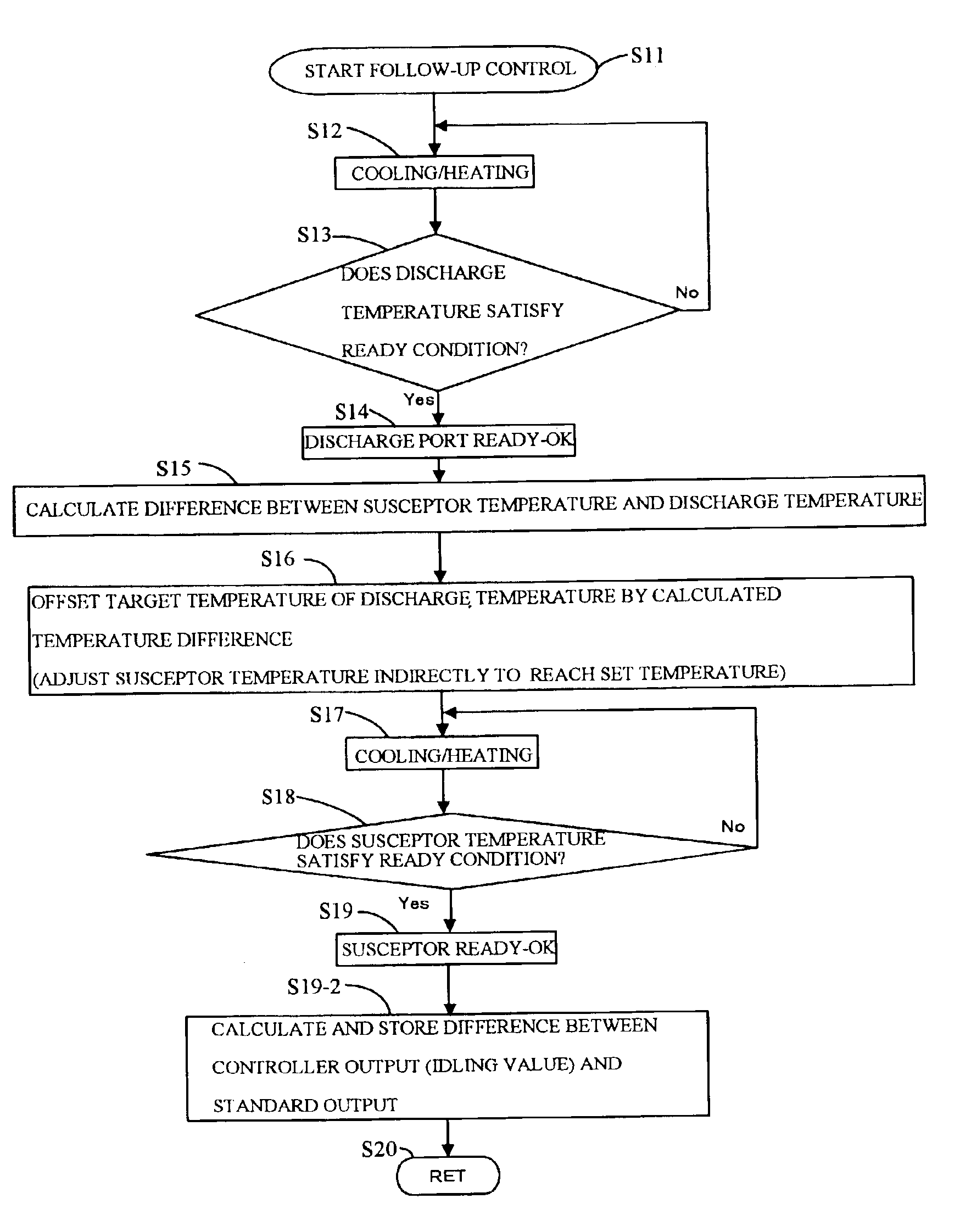
[0012]According to this temperature controlling device, not only the temperature of the heat transfer fluid, but also the temperature of the object is detected, and both temperatures are used to control the temperature of the heat transfer fluid. As a result, variation in the temperature of the object can be suppressed to a large extent, whereby the temperature can be controlled with a greater degree of constancy.
[0013]In a preferred embodiment, the cooler / heater cools or heats the heat transfer fluid using a thermoelectric conversion device. By using a thermoelectric conversion device, the cooler / heater can be reduced in size, and the distance between the cooler / heater and the object can be reduced, thereby enabling a reduction in the volume of heat transfer fluid. Further, the responsiveness and temperature control precision of the thermoelectric conversion device itself are high, resulting in the attainment of high controllability.
[0020]According to this temperature controlling device, variation in the temperature of an object can be suppressed to a large extent, whereby the temperature can be controlled to a set temperature.

Problems solved by technology

According to this conventional method of controlling the discharge temperature of heat transfer fluid to a set temperature, it is difficult to suppress a large rise in the temperature of the susceptor when a thermal load (disturbance) is applied to the susceptor at the beginning of plasma processing in the processing chamber.
To explain in more general terms, when controlling the discharge temperature of heat transfer fluid, it is difficult to sufficiently suppress temperature variation in the object of temperature control when a thermal load is applied to this object.
Also according to such discharge temperature control, the temperature of an object of temperature control such as a susceptor may vary greatly due to the effects of heat loss or heat resistance, or due to wasted time, delays and the like, in the piping or chambers existing on the outside of the temperature controlling device.
However, since the temperature of the object of temperature control is controlled indirectly via the heat transfer fluid, it is difficult to reduce temperature variation in the object of temperature control when the control operation is performed based only on the temperature of the object of temperature control itself.

Method used


Image

  • Method and device for controlling the temperature of an object using heat transfer fluid
  • Method and device for controlling the temperature of an object using heat transfer fluid
  • Method and device for controlling the temperature of an object using heat transfer fluid

Examples


Embodiment Construction

[0035]An embodiment of the present invention will be described below. The following embodiment is an example of a case in which the present invention is implemented in an application in which the temperature of a susceptor used for supporting a semiconductor wafer inside a processing chamber for processing a semiconductor wafer in a plasma atmosphere is controlled to a constant level. However, the scope of the present invention is not limited to this example, and the present invention may be implemented in various other applications.

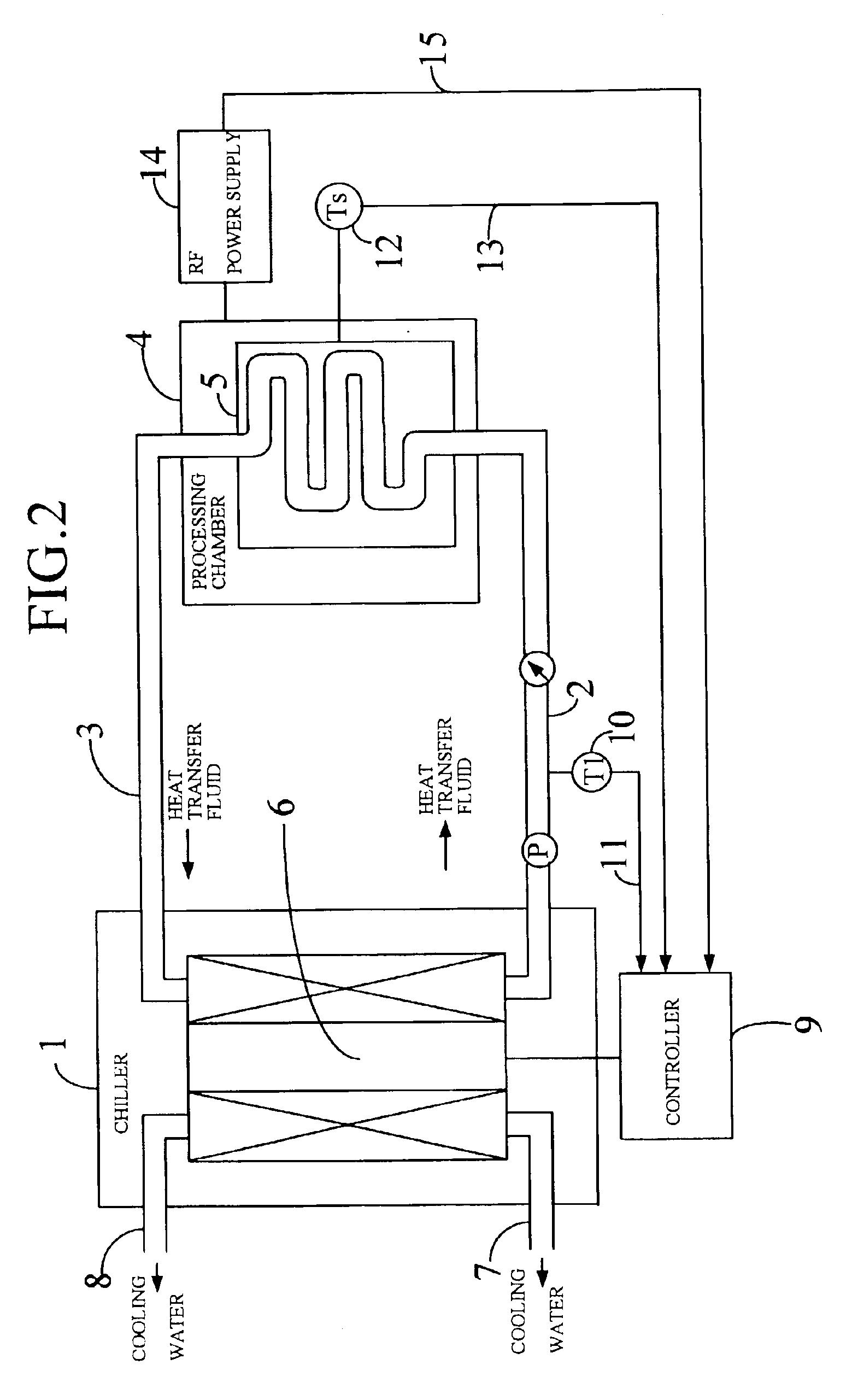
[0036]FIG. 2 shows the overall constitution of this embodiment.

[0037]A chiller 1 for cooling heat transfer fluid is disposed in a location removed from a processing chamber 4 by one to several meters, for example. Heat transfer fluid which has been temperature controlled by the chiller 1 is discharged from the chiller 1 and supplied to the processing chamber 4 through piping 2. For example, water, ethylene glycol, Fluorinert (registered trademark), and s...


PUM


Abstract

An object of the present invention is to suppress to a sufficiently small level variation in the temperature of an object in a case where the temperature of an object is controlled to a desired value using heat transfer fluid. A controller (9) controls the power of a thermoelectric conversion device (6) which is used for cooling or heating heat transfer fluid supplied to an object (5). The controller (9) performs a feedback control operation using the temperature (T1) of the heat transfer fluid emitted from the thermoelectric conversion device (6) and the temperature (Ts) of the object. In this feedback control operation, the difference between the object temperature (Ts) and the heating medium temperature (T1) is added to a set temperature (SV), whereby a target temperature of the heating medium temperature (T1) is calculated. By means of an I-PD calculation with respect to the deviation between this target temperature and the heating medium temperature (T1), a manipulated variable to be applied to the cooler / heater (6) is calculated. Prior to the beginning of this feedback control operation, an initial value of the aforementioned manipulated variable is calculated in accordance with the magnitude of a thermal load to be applied to the object (5) from outside during the control operation and the set temperature (SV). The feedback control operation begins upon the output of this initial value.

Description

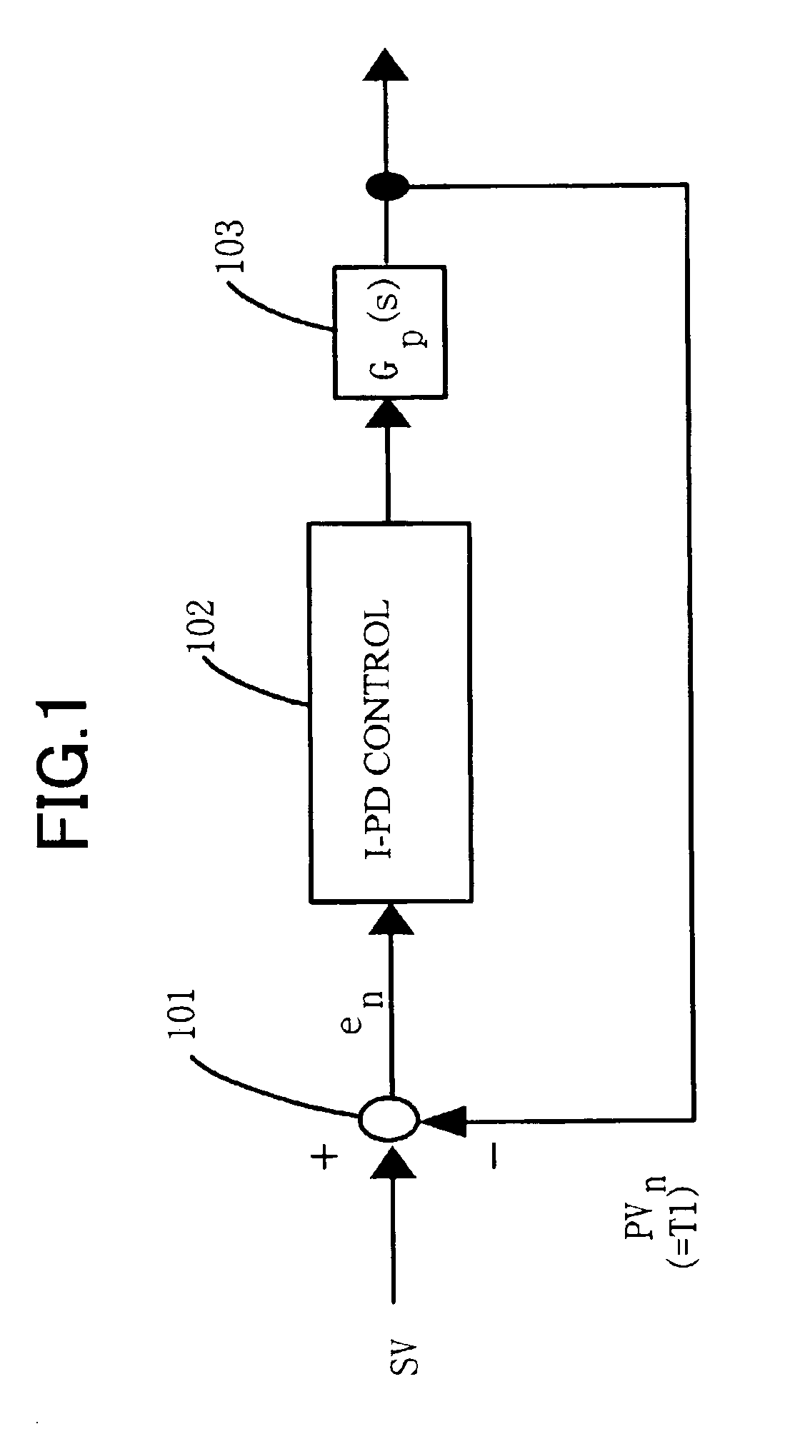
BACKGROUND OF THE INVENTION[0001]1. Field of the Invention[0002]The present invention relates to a method and device for controlling the temperature of an object using heat transfer fluid.[0003]2. Description of the Related Art[0004]Temperature-controlled heat transfer fluid is used in a processing chamber for processing a semiconductor wafer in a plasma atmosphere in order to control the temperature of a table on which the semiconductor wafer is placed (to be referred to hereafter as “susceptor”). The heat transfer fluid is brought to an appropriate temperature using a temperature adjusting device (for example a chiller for cooling high-temperature heat transfer fluid returned from a chamber) which is disposed in a location removed from the chamber, and then transferred from the device to the chamber and circulated around the susceptor. The heat transfer fluid is then removed from the chamber and returned to the temperature adjusting device.[0005]As is illustrated in FIG. 1, this t...

Claims


Application Information

Patent Timeline
IPC IPC(8): G05B11/42G05B13/02
CPCG05B13/024G05B11/42H01L21/02
Inventor SEKI, MASANOBUSASAKI, JUN
Owner KOMATSU LTD
Learn More