

Control device and control method for internal combustion engine with supercharger
- Summary
- Abstract
- Description
- Claims
- Application Information
AI Technical Summary
Benefits of technology
Problems solved by technology
Method used
Image

Examples
first embodiment
[0027]the present invention will be first described below with reference to the drawings.
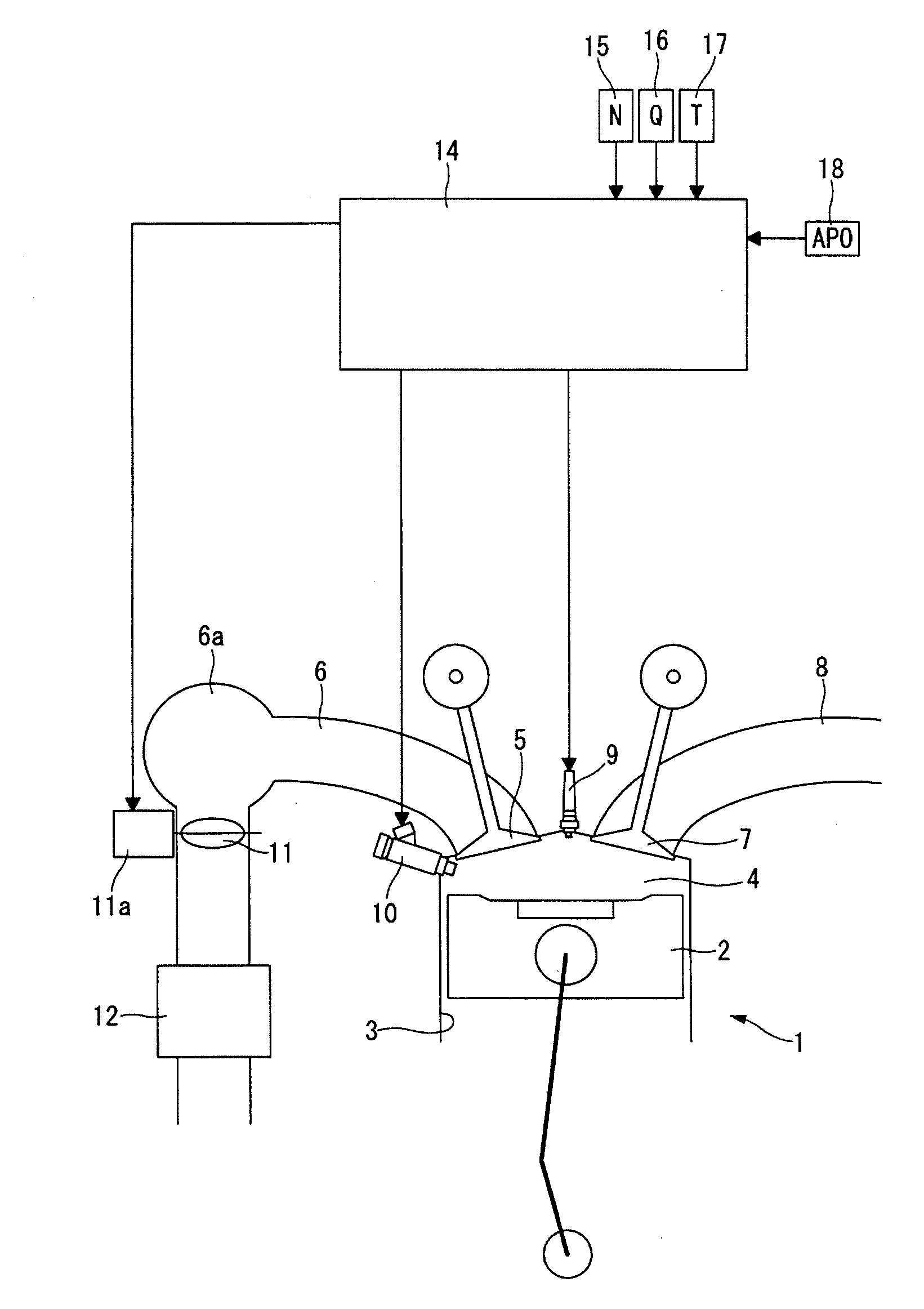
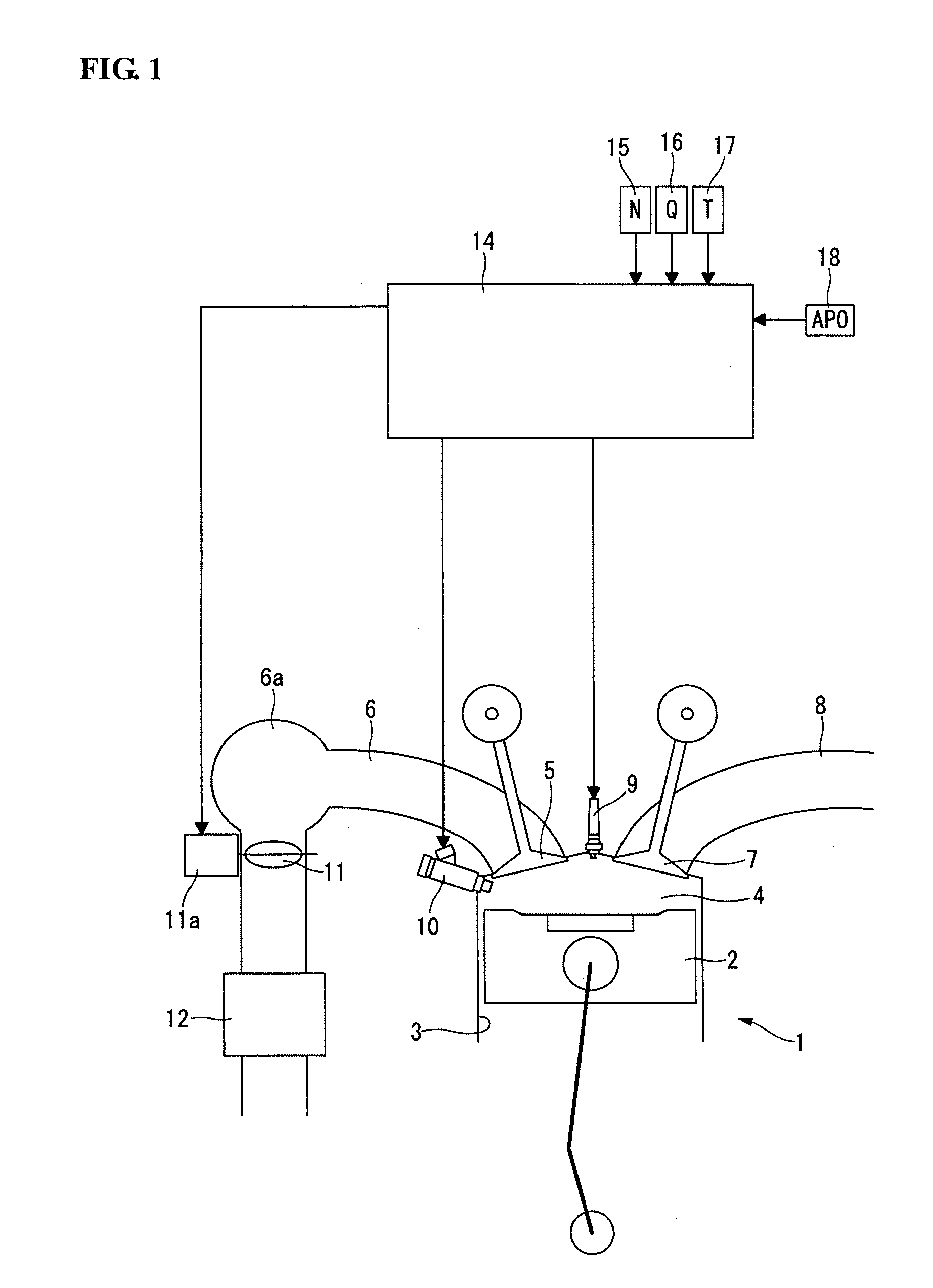
[0028]FIG. 1 is a schematic view of a supercharger-equipped internal combustion engine 1 according to the first embodiment of the present invention. In the internal combustion engine 1, a piston 2 is arranged in a cylinder bore 3 to define a combustion chamber 4; and an intake passage 6 and an exhaust passage 8 are connected to the combustion chamber 4 via an intake valve 5 and an exhaust valve 7, respectively.
[0029]A spark plug 9 is arranged in a ceiling wall of the combustion chamber 4. A fuel injection valve 10 is arranged in one side of the combustion chamber 4 so as to directly inject fuel into the combustion chamber 4.
[0030]A throttle valve 11 whose opening is adjusted by an actuator 11a such as electric motor is located upstream of a collector 6a in the intake passage 6. Further, a supercharger 12 is located upstream of the throttle valve 11 in the intake passage 6. As the supercharger 12...
second embodiment
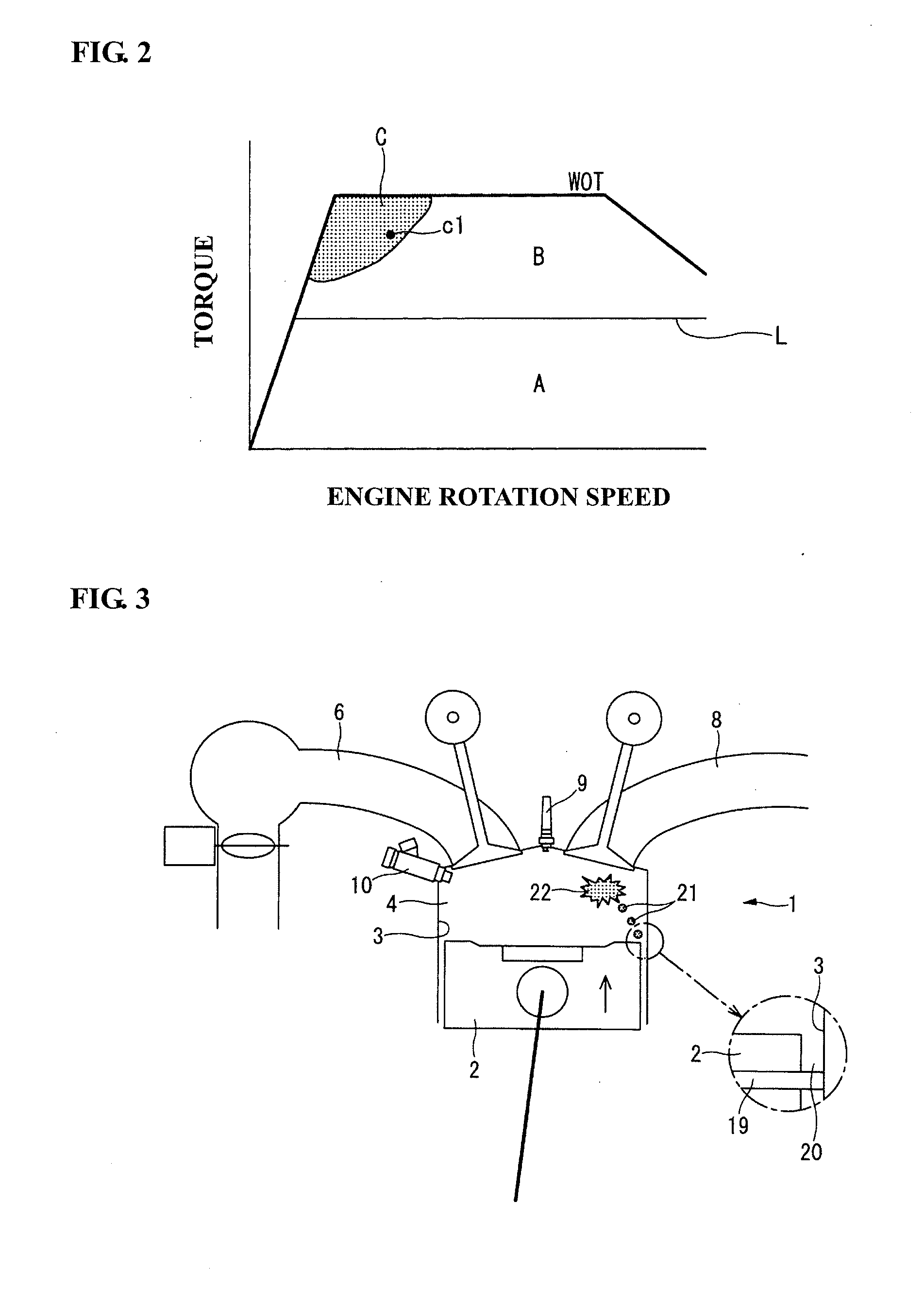
[0040]In the second embodiment, the above-mentioned abnormal combustion is prevented by decreasing the mechanical compression ratio as shown in FIG. 7. FIG. 7 is a schematic diagram similar to FIG. 5. At the specific load and rotation speed operation point cl in the region C during warm-up operation before the completion of engine warm-up, the variable compression ratio mechanism 31 is operated to decrease and correct the mechanical compression ratio to a lower value than that after the completion of engine warm-up. The rate of correction of the mechanical compression ratio is set larger as the cylinder bore wall temperature T is lower. Namely, the lower the cylinder bore wall temperature T, the lower the mechanical compression ratio, so that the temperature of the air-fuel mixture in the vicinity of the compression top dead center can be suppressed. As the operation point c1 in in the high-load range, the mechanical compression ratio is controlled to a relatively low value at the o...
fourth embodiment
[0045]In the fourth embodiment, the exhaust gas recirculation control valve 52 is operated in such a manner that, when the load and rotation speed operation point of the internal combustion engine 1 is in the region C, the amount of recirculation of the exhaust gas is set larger as the cylinder bore wall temperature T is lower as in the case of FIGS. 5 and 7. The heat capacity ratio of the air-fuel mixture inside the cylinder is decreased by the recirculation of the exhaust gas. It is thus possible to decrease the temperature of the air-fuel mixture in the vicinity of the compression top dead center even if the recirculated exhaust gas is higher in temperature than the intake air. As the temperature of the recirculated exhaust gas is decreased by the EGR gas cooler 53, the use of the EGR gas cooler 53 is more effective to suppress the temperature of the air-fuel mixture in the vicinity of the compression top dead center.
[0046]A fifth embodiment of the present invention will be descr...
PUM
 Abstract
Description
Claims
Application Information