Lubricant composition and lubricating method

Inactive Publication Date: 2018-11-15
IDEMITSU KOSAN CO LTD
View PDF5 Cites 2 Cited by
  • Summary
  • Abstract
  • Description
  • Claims
  • Application Information

AI Technical Summary

Benefits of technology

[0023]The lubricating oil composition of the present invention has a high flash point of 250° C. or higher and has an excellent long lifetime to su

Problems solved by technology

The lubricating oil composition used for a long period of time in high-temperature environments often involves risks of performance degradation owing to oxidation and sludge precipitation owing to oxidation.
The precipitated sludge may cause pr

Method used


Image

  • Lubricant composition and lubricating method

Examples


Example

Examples 1 to 3 and Comparative Examples 1 to 2

[0167]The refined paraffinic mineral oils (1) to (3) and the alkylbenzene having properties shown in Table 1, and various additives for a lubricating oil shown below were blended in the ratio shown in Table 2, and well mixed to produce lubricating oil compositions (I) to (V).

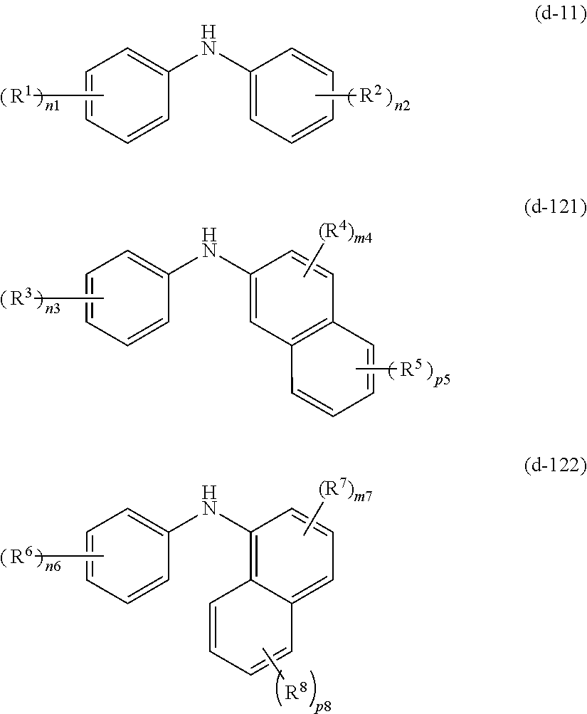
[0168]The details of the additives for a lubricating oil used in Examples and Comparative Examples, as shown in Table 2, are as follows.

(Anti-Foaming Agent)

[0169]Polyacrylate-based anti-foaming agent (1): solution having a resin concentration of 1% by mass, prepared by diluting polymethacrylate having Mw of 48000 with light oil.

Polyacrylate-based anti-foaming agent (2): polymethacrylate having Mw of 51000.

Silicone-based anti-foaming agent: solution having a resin concentration of 1% by mass, prepared by diluting polydimethylsilicone having a kinematic viscosity at 25° C. of 12500 mm2 / s with light oil.

(Antioxidant)

[0170]Amine-based antioxidant (1): dioctyldiphenylami...


PUM

PropertyMeasurementUnit
Temperatureaaaaaaaaaa

Abstract

Provided is a lubricating oil composition containing a refined paraffinic mineral oil (A) and an alkylbenzene (B) having a flash point of 160° C. or higher, and having a flash point of 250° C. or higher. The lubricating oil composition has a high flash point of 250° C. or higher and has an excellent long lifetime to such an extent that the lubricating oil composition can maintain excellent oxidation stability even in long-term use in high-temperature environments.

Description

TECHNICAL FIELD[0001]The present invention relates to a lubricating oil composition, and to a lubricating method using the lubricating oil composition.BACKGROUND ART[0002]A lubricating oil composition for use for turbines such as steam turbines, gas turbines, etc., rotary gas compressors, hydraulic machines and the like is used to circulate in a system in high-temperature environments for a long period of time.[0003]The lubricating oil composition used for a long period of time in high-temperature environments often involves risks of performance degradation owing to oxidation and sludge precipitation owing to oxidation. The precipitated sludge may cause problems of, for example, damage to bearings owing to heat generation after adhesion to rotor bearings, occurrence of clogging of filters arranged in circulation lines, control system operation failure owing to deposition on control valves, etc.[0004]Consequently, a lubricating oil composition for use for turbines, rotary gas compres...

Claims


Application Information

Patent Timeline
IPC IPC(8): C10M169/04C10M101/02C10M105/06C10M111/02C10M145/10C10M155/02C10M133/12C10M161/00
CPCC10M169/044C10M101/02C10M105/06C10M111/02C10M145/10C10M155/02C10M133/12C10M161/00C10M2203/1025C10M2203/065C10M2209/084C10M2229/02C10M2215/26C10N2230/18C10N2230/10C10N2230/02C10N2240/14C10N2240/30C10N2240/08C10M2205/06C10M2215/064C10M2215/065C10M2215/066C10N2030/02C10N2030/10C10N2030/18C10N2040/08C10N2040/30C10N2040/135
Inventor SHINODA, JITSUO
Owner IDEMITSU KOSAN CO LTD
Why Eureka
Try Eureka