
Synchronizer for power converters based on a limit cycle oscillator

a technology of limit cycle oscillator and synchronizer, which is applied in the direction of photovoltaic energy generation, pulse automatic control, ac network circuit arrangement, etc., can solve the problem of not being able to adapt to the frequency by itsel

Active Publication Date: 2018-11-15
INST POTOSINO DE INVESTIGACION CIENTIFICA Y TECHCA A C
View PDF0 Cites 5 Cited by
  • Summary
  • Abstract
  • Description
  • Claims
  • Application Information

AI Technical Summary

Benefits of technology

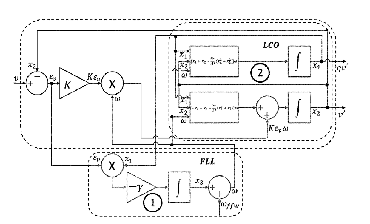
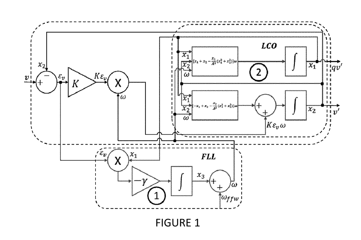
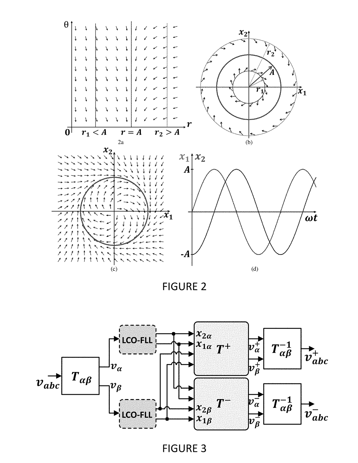
The invention relates to a system that generates a pure sinusoidal signal with a specific frequency through a lock-in control. This system uses an FLL frequency loop to keep the LCO set to the frequency and phase of the input signal. The invention proposes trajectories of the LCO that create free references of harmonics and disturbances of the electric network. These references allow for accurate monitoring and measurement of the electric network's operational range. The technical effect of this invention is to provide a reliable and accurate reference for monitoring and measuring electric networks.

Problems solved by technology

The LCO can be understood as the implementation of a filter, however, it is not adaptable to the frequency by itself.

Method used


Image

  • Synchronizer for power converters based on a limit cycle oscillator
  • Synchronizer for power converters based on a limit cycle oscillator
  • Synchronizer for power converters based on a limit cycle oscillator

Examples


example 1

[0056]A test was made to see the trajectory of the transient of both systems. Table I shows the initial conditions and the parameters of the LCO-FLL and the SOGI-FLL, which are the same for both systems. The frequency value of the reference was set at 60 Hz.

TABLE IProgramming parameters of LCO-FLL and SOGI-FLLParameterValuek, y1wffw377 rad / seg(x01, x02, x03)(10, 10, 10)v (Reference)sin(377t)

[0057]The test with the parameters of Table I is shown in FIG. 5 (a), in which the trajectories of the reference (Ch1), LCO-FLL (Ch3), and the SOGI-FLL (Ch4) are shown. FIG. 5 (b) shows the voltage error between the reference and the LCO-FLL; Here you can see that the transient time to synchronize it with the reference lasts approximately ˜9 ms, plus the error is monotonously decreasing. On the other hand, in FIG. 5 (c), an overdraft in the voltage error between the reference and the SOGI-FLL is shown before the error begins to decrease, which is an unwanted transition.

example 2

[0058]This test is performed to compare the transient of the frequency signal for both systems: LCO-FLL and SOGI-FLL, by varying the frequency of the reference. The test was performed as follows: The frequency of the input reference signal (9) changes from 45 Hz to 65 Hz (FIG. 6 (a)), and from 65 Hz to 45 Hz (FIG. 6 (b)). As can be seen in FIG. 6, the characteristics and advantages of the FLL are preserved after interconnection with the LCO, since the adaptability and dynamic behavior of the transient of the LCO-FLL are similar to that of the SOGI-FLL due to the that use the same frequency adaptation system.

example 3

[0059]This test is performed to observe the performance of both systems against a highly contaminated reference. A highly contaminated input reference was generated with the 2nd, 3rd, 5th, and 9th harmonics, with the percentage indicated in FIG. 7 (a). The total harmonic distortion (THD) of the input voltage is 20%. The behavior of both systems, LCO-FLL and SOGI-FLL can be seen in FIG. 7 (b). Both methods have good filtering characteristics, however the LCO-FLL has a better performance than the SOGI-FLL in terms of the reduction of harmonic disturbances, as can be seen in FIG. 7 (a). In addition, the THD for the LCO-FLL is 5.5%, which is better than the THD of the SOGI-FLL, which was 7.2%.


PUM


Abstract

The present invention presents a real-time synchronization system for power converters interconnected with the electrical network, whose operation is based on a structurally stable limit cycle oscillator and which develops pure sinusoidal trajectories, creating references free of harmonics and disturbances in network. The proposed invention has the advantage that it has a high degree of immunity and robustness within highly contaminated networks, either due to the presence of harmonics or other types of contamination that may exist in the network, with a better performance than the systems previously reported. Another advantage of the present invention is that regardless of the initial conditions that are established, the system always synchronizes with the signal of the network, guaranteeing a smooth transient from any initial condition to the limit cycle, so it does not require prior tuning. In addition, the proposed scheme does not require Phase-Locked Loop (PLL) or trigonometric functions for synchronization, thus reducing computational time and resources.

Description

FIELD OF THE INVENTION[0001]The instant invention belongs to the electric field, specifically to real time synchronization for power converters interconnected to the electric net.BACKGROUND OF THE INVENTION[0002]The instant invention discloses a synchronization system for power converters interconected to the electric grid which function is based in a non-linear oxcillator that behaves as a limit cycle oscillator. Generally, in each power convertor connected with the grid, such as active power filters, the Distributed Power Generation Systems (DPGSs), static VAR compensators (VAR), and uninterruptible power supplies (UPSs), needs a phase or frequency tracking system to provide a reference signal in order to synchronize with the grid voltage. In certain applications (e.g.) DPGSs,) it is critical a synchronization system with a high degree of immunity to harmonics unbalances, and power systems disturbances.[0003]In voltage power grids, the waves are sinusoidal and balanced under optim...

Claims


Application Information

Patent Timeline
IPC IPC(8): H03L7/099H02J3/38
CPCH03L7/099H02J3/381H02J3/40H02J2300/24Y02E10/56H02J3/38
Inventor FEMAT FLORES, ALEJANDRO RICARDOVAZQUEZ NAVA, NIMRODVAZQUEZ OVIEDO, ERICK ISRAEL
Owner INST POTOSINO DE INVESTIGACION CIENTIFICA Y TECHCA A C
Learn More