

Electrical power conversion apparatus
- Summary
- Abstract
- Description
- Claims
- Application Information
AI Technical Summary
Benefits of technology
Problems solved by technology
Method used
Image

Examples
first embodiment
[0038]Referring now to the drawings, wherein like reference numbers will refer to like parts throughout the several views, particularly to
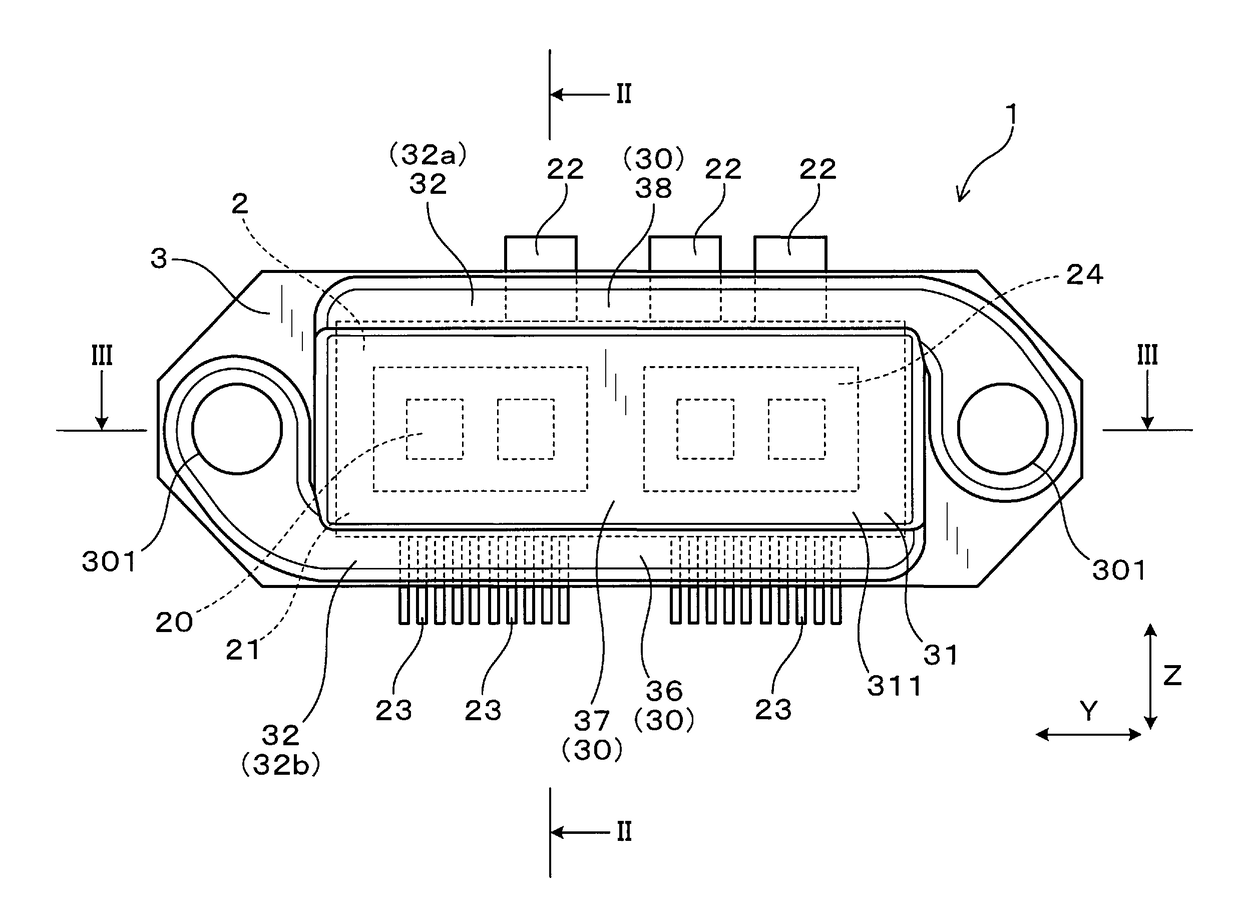
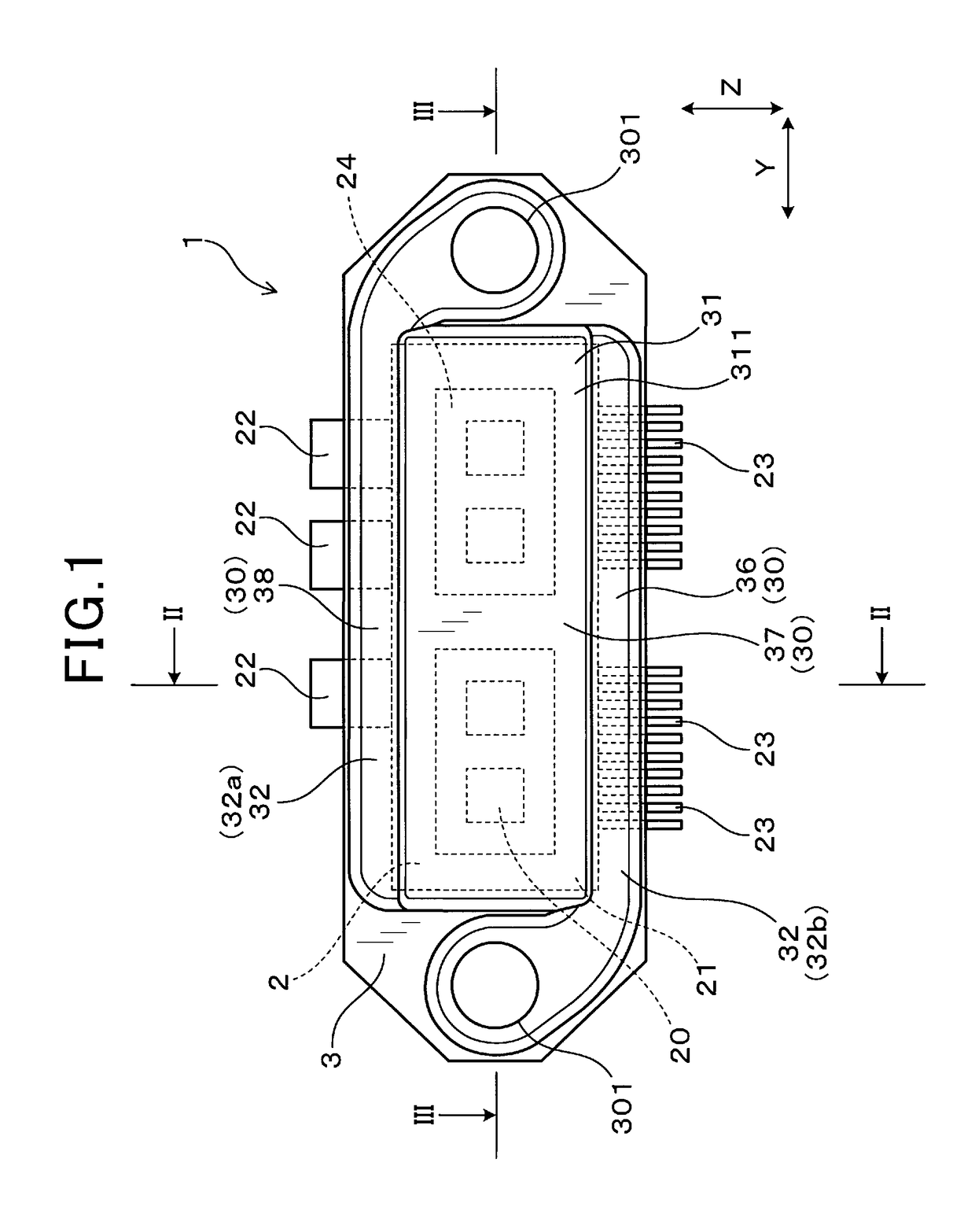
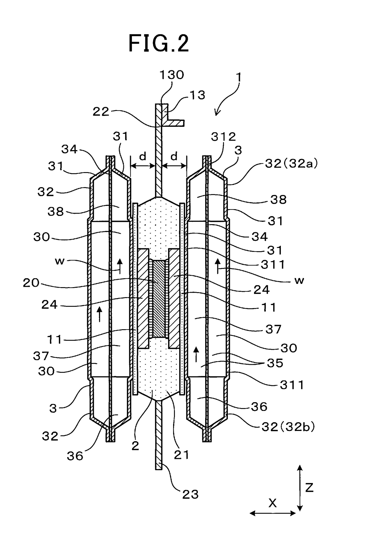
[0039]FIGS. 1 to 9, there is shown the electrical power conversion device 1 according to the first embodiment. The electrical power conversion device 1 is, as illustrated in FIGS. 1 to 3, equipped with the semiconductor modules 2 and a plurality of cooling pipes (i.e., cooling tubes) 3 which are stacked to hold major opposed surfaces of each of the semiconductor modules 2 therebetween.
[0040]Each of the semiconductor module 2 is equipped with the module body 21 in which the semiconductor device 20 is installed, a plurality of power terminals 22 protruding from the module body 21, and a plurality of control terminals 23 protruding from the module body 21.
[0041]Each of the cooling pipes 3 has electrical conductivity and is equipped with the cooling medium flow path 30 which is designed to have a cooling medium flowing therethrough.
[0042]The power ter...
second embodiment
[0090]FIG. 10 illustrates the electrical power conversion device 1 according to the second embodiment which is designed to have the cooling medium supply path 36 overlapping the power terminals 22 in the stacking direction X and also have the cooling medium draining path 38 overlapping the control terminals 23 in the stacking direction X.
[0091]Other arrangements are identical with those in the first embodiment, and explanation thereof in detail will be omitted here. In the second and following embodiments, the same reference numbers, as employed in the preceding embodiment, refer to the same parts unless otherwise specified.
[0092]In operation, after entering each of the cooling pipes 3, the cooling medium w is delivered into the cooling medium supply path 36 in the flow path extension forming portion 32 facing the power terminals 22 before it exchanges the thermal energy with the module body 21 through the heat exchanger 37. This causes the lower-temperature cooling medium w to flow...
third embodiment
[0094]FIG. 11 illustrates the electrical power conversion device 1 according to the third embodiment which is designed to have a plurality of semiconductor modules 2 aligned in the lateral direction Y between each two of the cooling pipes 3 adjacent in the stacking direction X.
[0095]The electrical power conversion device 1 has the semiconductor modules 2 each of which is equipped with a single switching device installed therein. Each two of the semiconductor modules 2 are arranged adjacent each other in the lateral direction Y and retained or firmly held by the two cooling pipes 3 opposed to each other in the stacking direction X.
[0096]Two of the semiconductor modules 2 which are arranged adjacent each other in the lateral direction Y respectively have, as illustrated in FIG. 12, the upper arm switching device 2u and the lower arm switching device 2d connected in series. The adjacent semiconductor modules 2 are, as illustrated in FIG. 11, arranged to have the power terminals 22O whi...
PUM
 Abstract
Description
Claims
Application Information