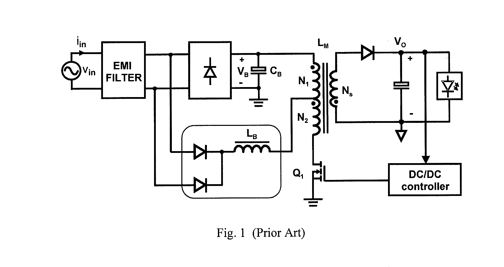
However,
voltage VB across bulk
capacitor CB is not regulated and at high line it can increase to impractical levels.
However, the tapping of the flyback primary winding also results in a zero-crossing
distortion of the
line current.
In fact, as long as the instantaneous line
voltage is lower than the voltage at the tapping point, no current is drawn from the input, which deteriorates the
power factor and the line-current
harmonics.
However, applying the single-stage PFC
flyback topology with a constant inductance LB in FIG. 1 for lighting applications, where the line-current
harmonics have to meet the more stringent limits set by the IEC 61000-3-2 Class C and JIS C 61000-3-2 Class C standards, presents a challenging task.
The difference between the output power and input power has to be supplied from the bulk
capacitor, causing a drop of the bulk-
capacitor voltage.
However, at low line (90-135 Vrms), if the boost inductance is larger than the maximum value for DCM operation, the boost inductor will enter CCM operation around the peak of the rectified line voltage, and the
line current waveform will have a bulge around its
peak value, resulting in an increased
total harmonic distortion (THD).
Furthermore, if the bulk-
capacitor voltage is slightly lower than the peak of the rectified line voltage, peak charging of the bulk capacitor through the bridge
rectifier will also result in a bulge in the
line current waveform with an increased THD.
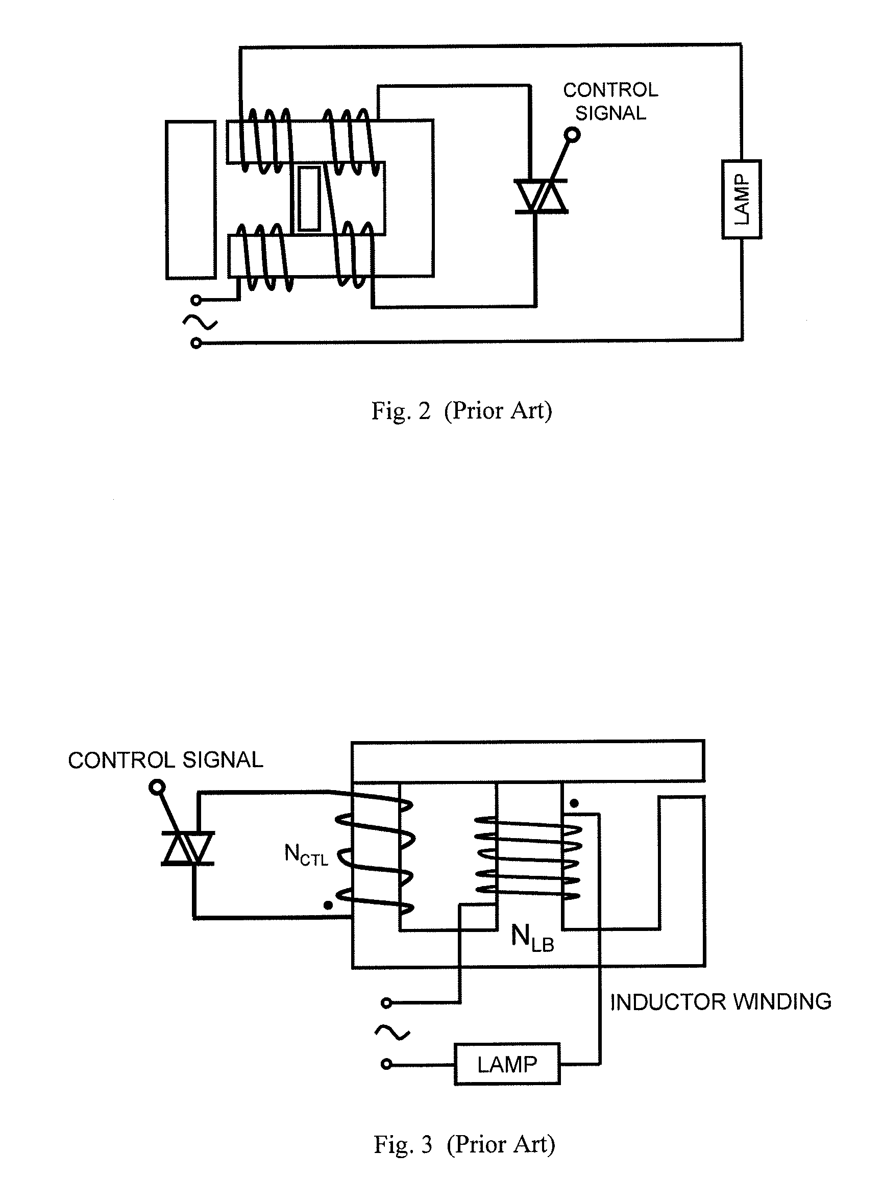
A major drawback of the methods disclosed in U.S. Pat. No. 3,873,910 and No. 4,162,428 is that a
short circuit is created when the
control switch is closed, resulting in a significant
power loss in the control winding and switch.
However, the inclusion of the
actuator requires a complex implementation.
Generally, manufacturing inductors with a stepped or sloped air gap is more complex than manufacturing inductors with a constant-length air gap, resulting in an increased cost.
However, the powdered
metal cores have significantly higher loss than the corresponding ferrite cores.
A drawback of this method is that the control winding is
strongly coupled with the inductor winding, resulting in undesired induced
ac current and, consequently,
power loss in the control winding.
Consequently, the total flux density variation through the control winding is not zero, resulting in undesired induced ac voltage and
power loss in the control winding.
The drawback of all current-controlled variable inductors in FIGS. 4, 6, and 8-10 is that the control winding is always coupled to the inductor winding.
Therefore the opposing fluxes do not completely cancel each other, resulting in undesired induced ac voltage and, consequently, increased power loss in the control winding.
In addition, any
asymmetry in the structure of the magnetic core and any mismatch in the two portions of the inductor winding or control winding further increase the unbalance between the opposing fluxes through the control winding and increase the undesired induced ac voltage and power loss in the control winding.
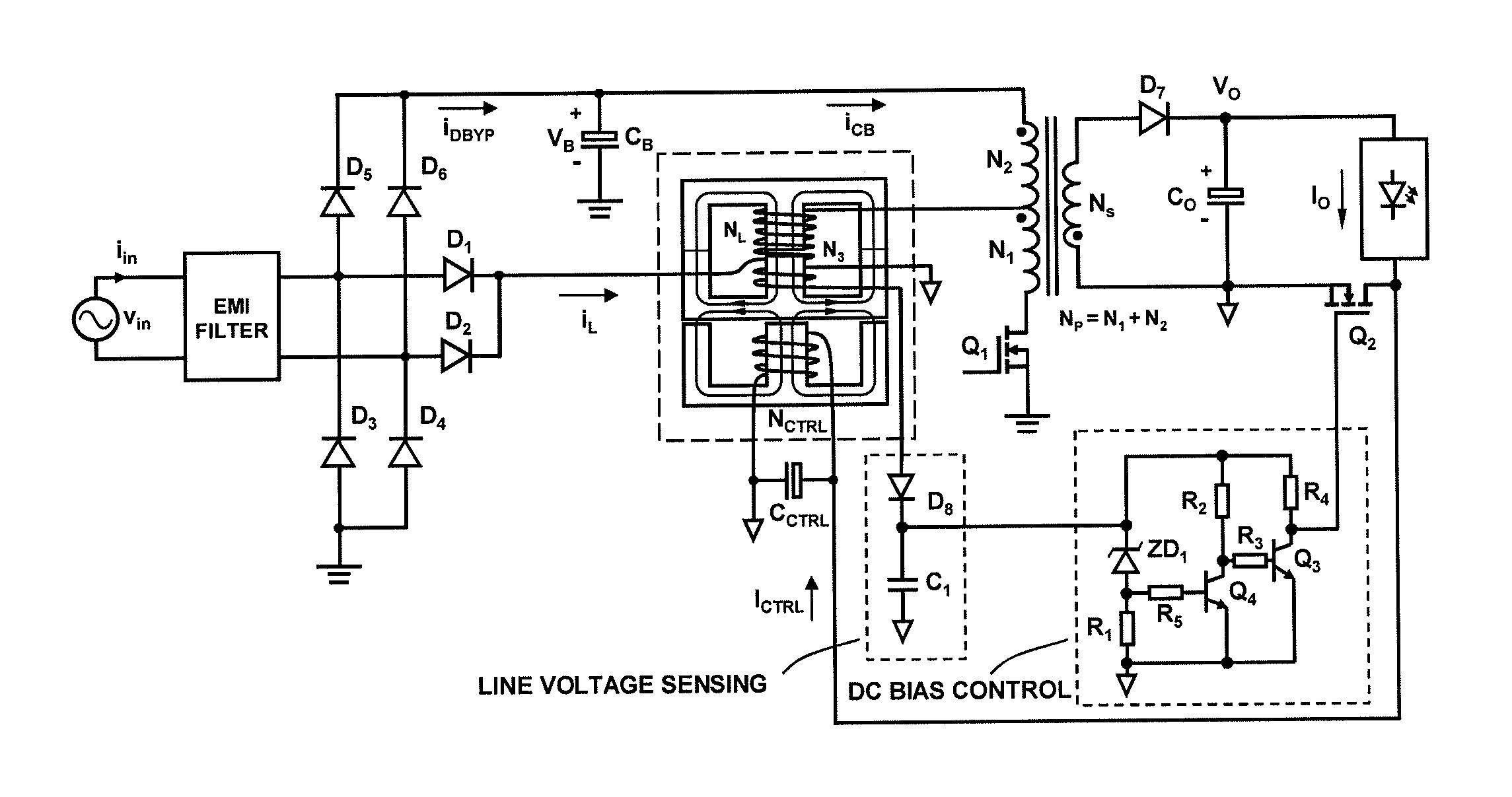
In
ripple-sensitive applications such as LED drivers, any additional
ripple in the LED current would adversely affect the
longevity of the LEDs.

