Control system of compression-ignition engine

a control system and compression ignition technology, applied in the direction of electric control, ignition automatic control, machines/engines, etc., can solve the problems of increased combustion noise, unburned mixture gas combusting by self-ignition,

Active Publication Date: 2018-11-22
MAZDA MOTOR CORP
View PDF0 Cites 24 Cited by
  • Summary
  • Abstract
  • Description
  • Claims
  • Application Information

AI Technical Summary

Benefits of technology

[0007]In this regard, the variation in the temperature inside the combustion chamber before the compression starts can be reduced by changing the heat generation amount in the SI combustion. For example, by changing the ignition timing to change the start timing of the SI combustion according to the temperature inside the combustion chamber before the compression starts, the timing of self-ignition can be controlled.
[0066]If the swirl flow is formed in the combustion chamber, the flow of the mixture gas inside the combustion chamber is stimulated and also the mixture gas in the combustion chamber is stratified. Thus, hazardous substances, such as NOx and soot, are prevented from being generated, and the mixture gas by which the SI combustion in the SPCCI combustion is stably performed is unevenly formed around the spark plug at an ignition timing. Therefore, the stable SPCCI combustion is achieved and NVH is suppressed below the allowable value also at a high engine speed.

Problems solved by technology

That is, mixture gas inside a combustion chamber is forcibly ignited to combust through flame propagation, and heat generated by this combustion causes unburned mixture gas to combust by self-ignition.
For example, if the timing of the self-ignition is advanced, the combustion noise increases.

Method used


Image

  • Control system of compression-ignition engine
  • Control system of compression-ignition engine
  • Control system of compression-ignition engine

Examples


Embodiment Construction

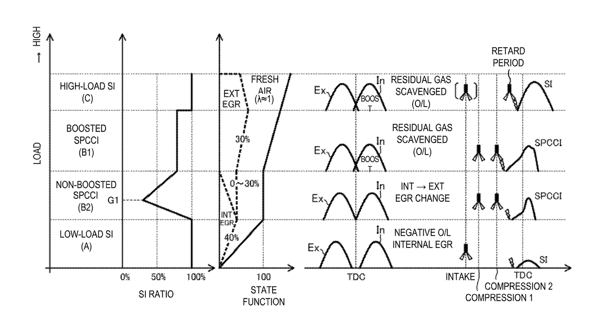
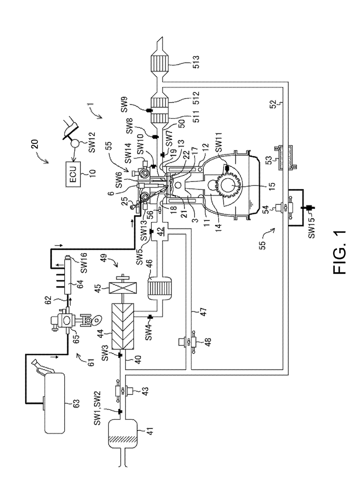
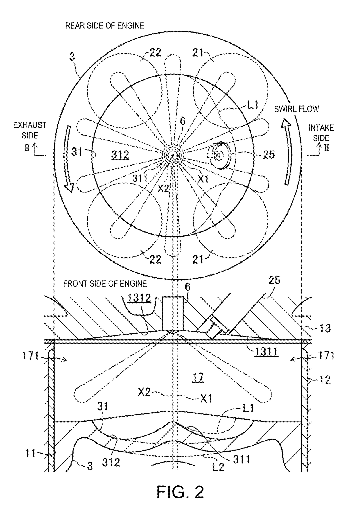
[0089]Hereinafter, embodiments of a control system of a compression-ignition engine (hereinafter, may simply be referred to as “engine 1”) are described in detail with reference to the accompanying drawings. The following description gives one example of the control system of the engine 1. FIG. 1 is a diagram illustrating a configuration of the engine 1. FIG. 2 is a cross-sectional view illustrating a structure of a combustion chamber. FIG. 3 is a plan view illustrating structures of the combustion chamber and an intake system. Note that in FIG. 1, an intake side is on the left side and an exhaust side is on the right side of the drawing sheet. Further in FIGS. 2 and 3, the intake side is on the right side and the exhaust side is on the left side of the drawing sheets. FIG. 4 is a block diagram illustrating a configuration of the control system of the engine 1.

[0090]Further, the definition of “EGR gas” used below includes “burned gas (exhaust gas) that remains in the combustion cham...


PUM


Abstract

A control system of a compression-ignition engine is provided, which includes an engine configured to cause combustion of mixture gas inside a combustion chamber, a spark plug, and a controller configured to operate the engine. The combustion is performed in a given mode in which, after the spark plug ignites the mixture gas to start combustion, unburned mixture gas combusts by self-ignition. The controller has a heat amount ratio changing module configured to change, according to an engine operating state, a heat amount ratio as an index relating to a ratio of a heat amount generated when the mixture gas combusts by flame propagation with respect to a total heat amount generated when the mixture gas inside the combustion chamber combusts. The controller causes the changing module to increase the heat amount ratio at a high engine speed than at a low engine speed.

Description

TECHNICAL FIELD[0001]The present disclosure relates to a control system of a compression-ignition engine.BACKGROUND OF THE DISCLOSURE[0002]JP4082292B discloses an engine for combusting a mixture gas inside a combustion chamber by self-ignition within a given operating range where an engine load and an engine speed are low. The engine combusts the mixture gas by spark-ignition within an operating range where the engine load is high and an operating range where the engine speed is higher than the given operating range.[0003]Incidentally, combustion caused by compression ignition accompanies a relatively loud combustion noise. When the engine speed is high, NVH (Noise Vibration Harshness) of the engine exceeds an allowable value.SUMMARY OF THE DISCLOSURE[0004]The present disclosure is made in view of the above situations and aims to perform combustion by compression ignition while suppressing NVH of a compression-ignition engine below an allowable value.[0005]As described later, the pr...

Claims


Application Information

Patent Timeline
Patent Type & Authority Applications(United States)
IPC IPC(8): F02M26/01F02B11/00F02P5/04F02D41/00
CPCF02M26/01F02B11/00F02P5/045F02D41/0002F02D2041/0015F02D13/02F02D13/0261F02D37/02F02D41/006F02D41/0065F02D41/08F02D41/3041F02D35/023F02D41/0052F02D2041/001F02D2200/101F02B23/0624F02B23/0669F02B23/0696F02B31/085F02P5/1502F02P5/1516Y02T10/12Y02T10/40
Inventor INOUE, ATSUSHIMATSUMOTO, KOTAKAWAI, YUSUKEMIYAMOTO, TORUKOSHIRO, YUDAI
Owner MAZDA MOTOR CORP
Why Eureka
Try Eureka