Cutting insert and indexable rotary cutting tool

a cutting tool and insert technology, applied in the field of cutting inserts, can solve the problems of shortened tool life and deterioration of the machined surface, and achieve the effects of reducing the cutting force, improving the surface roughness of the machined surface, and reducing the vibration of the tool

Active Publication Date: 2018-11-29
HITACHI TOOL ENG LTD
View PDF25 Cites 15 Cited by
  • Summary
  • Abstract
  • Description
  • Claims
  • Application Information

AI Technical Summary

Benefits of technology

[0061]The cutting edge portions provided in the cutting insert of the present invention are each configured in a state where the corner edge, the major cutting edge formed into a straight line, the first minor cutting edge formed into a circular arc, and the second minor cutting edge formed in to a straight line are continuous in this order as one cutting edge. The indexable rotary cutting tool of the present invention to which the cutting insert of the present invention with such configuration is attached exerts the following effects.
[0062]The effect of the first aspect of the present invention is that, when the rake face near the second minor cutting edge is viewed in the cross-section thereof, this rake face is formed into a convex shape with respect to the reference plane, and thereby the chip discharge performance is improved and wear and deformation of the reference plane due to contact with chips or the like can be avoided in a ramping milling using the second minor cutting edge. Thus, since a concave portion and a vertical wall face are not present on the rake face near the second minor cutting edge, clog of the chips due to the vertical wall face can be avoid. As a result, the cutting force is reduced, and thus it is possible to reduce a chatter vibration of the tool and improve a surface roughness of the machined surface.
[0063]The effect of the second aspect of the present invention is that the end portions of the cutting edges (S1, S2 and S3) can be prevented from being preferentially worn since the cutting edges constituting each cutting edge portion are smoothly continuous. Thereby, the shape of the cutting edge portion is maintained for a long term and thus the cutting performance can be maintained.
[0064]The effect of the third aspect of the present invention is that chips generated during a cutting can be flowed to radially inward of the indexable cutting tool, since the breaker surface as the rake face of the cutting edge portion is configured so that the rake angle thereof near the first corner edge is small and that near the second minor cutting edge is large. Thereby, even in a cutting where the long-side-direction side surface of the cutting insert comes close to the vertical wall of a workpiece, the chips can be prevented from being involved between the vertical wall and the long-side-direction side surface.
[0065]The effect of the fourth aspect of the present invention is that the cutting force of the second minor cutting edge can be reduced, since the intersecting angle γ is set to be 70≤γ<90. Further, in the ramping milling using the second minor cutting edge, the chip discharge performance can be favorable.
[0066]The effects of the fifth and sixth aspects of the present invention are that the strength of the second minor cutting edge can be improved, since the rake face of the second minor cutting edge is formed into a convex shape with respect to the reference plane when the rake face of the second minor cutting edge is viewed from the cross-section thereof. Accordingly, since the fracture resistance of the edge tip is improved, high-feed conditions can be set in the ramping milling using a second minor cutting edge.

Problems solved by technology

However, in the high-feed cutting, a large load of the cutting (cutting force) is applied to the cutting insert, and thus there are some trouble where early wear of the rake face and the flank face of the cutting edge and chipping and fracture of cutting edge of the cutting insert occur, and thus quality of the machined surface is deteriorated and the tool life of the cutting insert is shortened.

Method used


Image

  • Cutting insert and indexable rotary cutting tool
  • Cutting insert and indexable rotary cutting tool
  • Cutting insert and indexable rotary cutting tool

Examples


first embodiment

[0095]The first embodiment of the present invention is a cutting insert in which high-feed conditions can be set especially in a ramping milling of a workpiece using a second minor cutting edge and the chip discharge performance can be improved, and an indexable rotary cutting tool in which the cutting insert is detachably attached to a tool main body. According to the indexable rotary cutting tool of the present embodiment, the surface roughness of the machined surface is improved even in a high-feed cutting, and the favorable machined surface can be obtained even in the ramping milling of the workpiece. Thus, the present embodiment is particularly suitable for the indexable rotary cutting tool for a high-feed rough machining on the workpiece.

[0096](Basic Configuration of Cutting Insert)

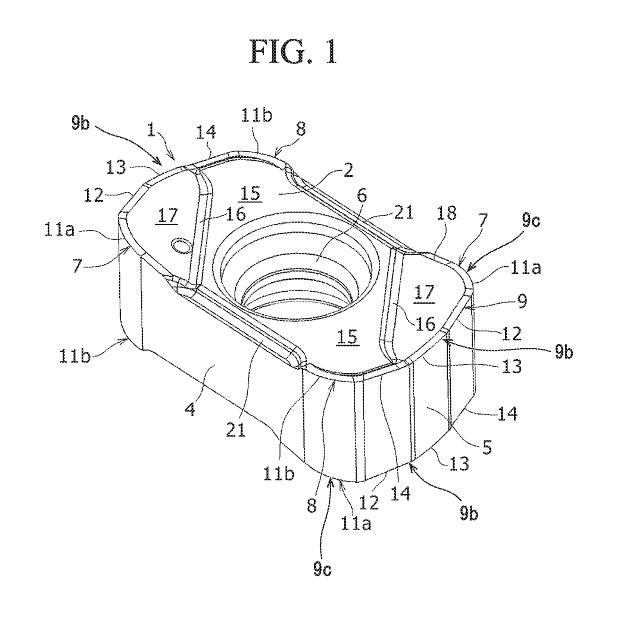
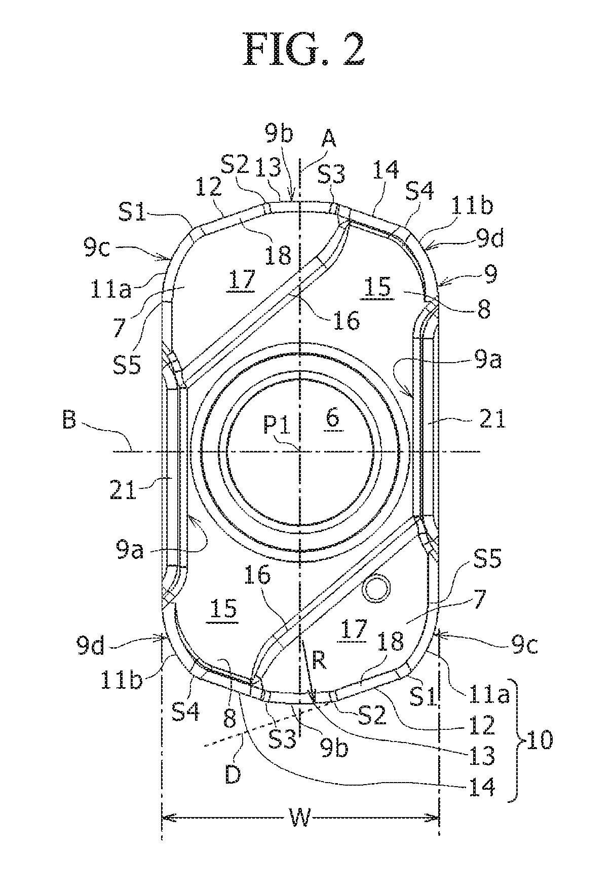
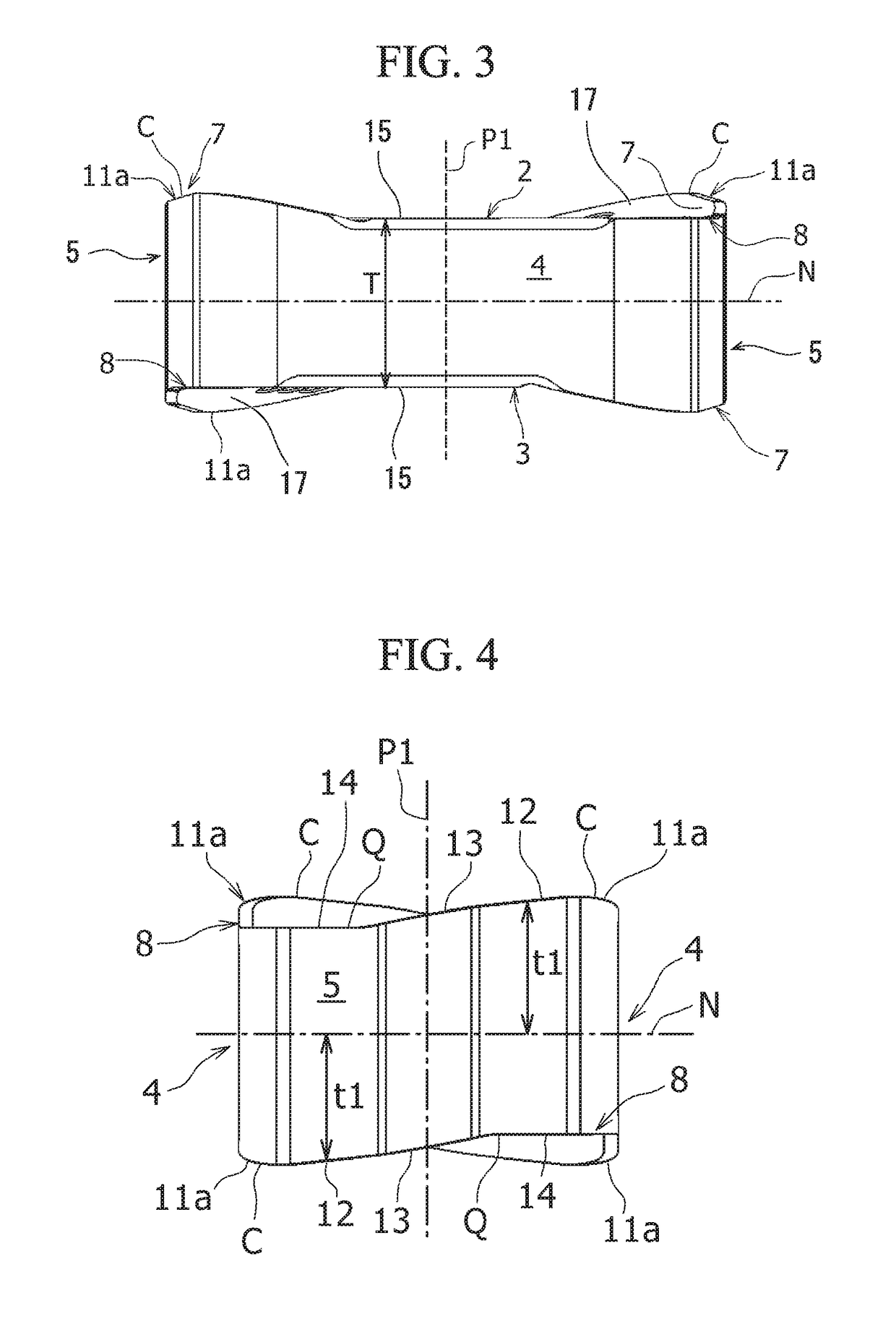
[0097]Hereafter, the basic configuration of the cutting insert according to the present embodiment will be described with reference to FIG. 1 to FIG. 5. FIG. 1 is a perspective view of a cutting ins...

second embodiments

[0183]Next, the cutting insert 101 according to the second embodiment of the present invention, and the indexable rotary cutting tool 130 including the same will be described with reference to FIG. 13 to FIG. 19. FIG. 13 is a perspective view of the cutting insert according to the present embodiment which is viewed obliquely from up above a top surface thereof. FIG. 14 is a plan view of the cutting insert shown in FIG. 13 which is viewed from the top surface thereof. FIG. 15 is a side view of the cutting insert shown in FIG. 13 which is viewed from a long-side-direction side surface thereof. FIG. 16 is a front view of the cutting insert shown in FIG. 13 which is viewed from a short-side-direction side surface thereof.

[0184]The parts common with the first embodiment is put into the same reference numerals and the descriptions thereof are simplified. In addition, regarding the parts of which reference numbers are different from the first embodiment but names are the same as in the fir...


PUM


Abstract

In the cutting insert of the present invention, the cutting edge portion includes: a first corner edge; a major cutting edge continuous with a first end portion (S1) of the first corner edge near the short-side-direction side surface and formed into a straight line; a first minor cutting edge continuous with a second end portion (S2) of the major cutting edge and formed into a circular arc; and a second minor cutting edge continuous with a third end portion (S3) of the first minor cutting edge and formed into a straight line. In a cross-sectional view of a rake face of the second minor cutting edge perpendicular to the second minor cutting edge, a cross-sectional ridgeline of the rake face of the second minor cutting edge is formed into a convex shape protruding above a cross-sectional ridgeline of a reference plane.

Description

TECHNICAL FIELD[0001]The present invention relates to a cutting insert in which, in a face milling performed on a workpiece, surface roughness of a machined surface is improved and a favorable machined surface can be obtained even in a high-feed ramping milling of a workpiece, and an indexable rotary cutting tool to which the cutting insert is detachably attached.BACKGROUND ART[0002]An indexable rotary cutting tool is practically used, in which a cutting insert made of cemented carbide (hereafter, referred to as “cutting insert”) including a cutting edge is detachably attached to an insert mounting seat formed at a tip portion of a cutting tool for a milling using a clamp screw. This indexable rotary cutting tool has a plurality of the cutting inserts attached thereto, and thus can perform a high-efficiency cutting on a workpiece under a high-feed cutting conditions, for example, where a feed per tooth is set to be about 0.8 to 1.0 (mm / tooth) when the workpiece is carbon steel or th...

Claims


Application Information

Patent Timeline
Patent Type & Authority Applications(United States)
IPC IPC(8): B23C5/20B23C5/10
CPCB23C5/207B23C5/109B23C2200/0494B23C2200/28B23C5/202B23C5/205B23C2200/291B23C2200/208B23C5/06
Inventor MURA, HISANORIHIBATA, TADAHIROMURATA, TOMOHIRONOSHITA, MASASHI
Owner HITACHI TOOL ENG LTD
Why Eureka
Try Eureka