Bag making machine

a bag making machine and bag technology, applied in the field of bag making machines, can solve the problems of low work efficiency, difficult setting before the bag making process, defective products, etc., and achieve the effect of facilitating setting and restricting the occurrence of defective products

Inactive Publication Date: 2018-11-29
NEW IWASHO CO LTD +1
View PDF0 Cites 17 Cited by
  • Summary
  • Abstract
  • Description
  • Claims
  • Application Information

AI Technical Summary

Benefits of technology

[0019]Accordingly, it is possible to restrict the occurrence of defective products by adjusting the tension, etc., of a film in accordance with a detection result. Since images of the two surfaces of a film throughout its width are acquired with the line sensors, there is no need to place a camera facing a specific portion of the film. Even when a print pattern on a film changes, it is possible to perform shooting while the line sensors are kept installed at the same position on the bag making machine. This facilitates settings before a bag making process.

Problems solved by technology

In such a case, when bags are made by sealing and cutting a film at initially set positions, sealing and cutting may not be performed at positions matching print patterns on the film, resulting in defective products.
However, visual inspections by operators lead to low work efficiency.
Since the position of the CCD camera needs to be changed for each of packing films with different print patterns, it is not easy to make settings before a bag making process.
This method is based on the assumption that the print pattern pitch on a sheet to be inspected is constant, but is not designed to inspect a sheet in the process of making bags.
Accordingly, the method gives no consideration to the expansion and contraction of sheets due to heat sealing and cooling, and hence cannot detect any change in print pattern pitch.

Method used


Image

  • Bag making machine
  • Bag making machine
  • Bag making machine

Examples


first embodiment

1. First Embodiment

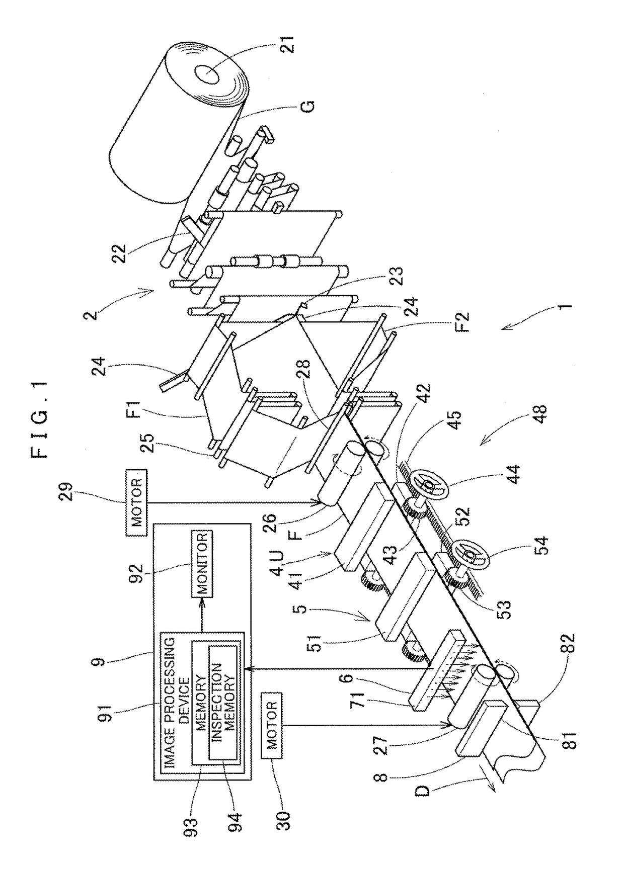
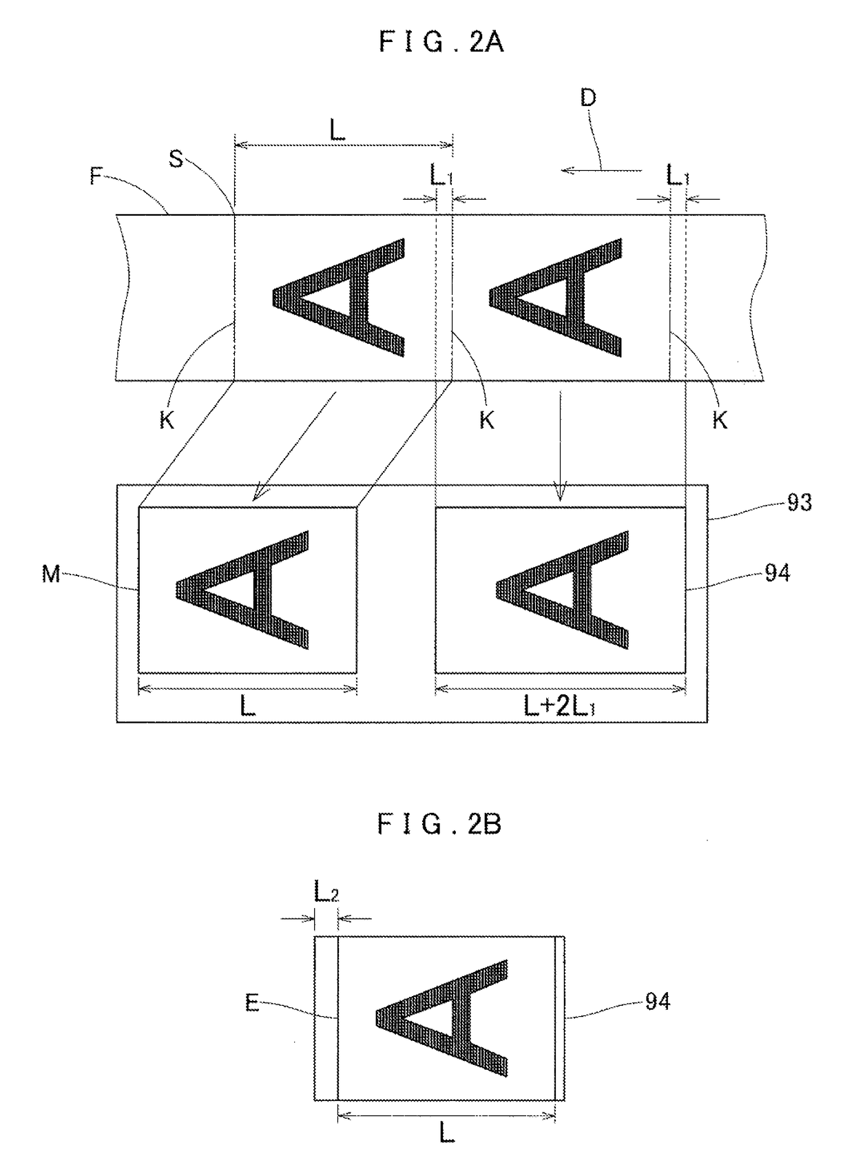
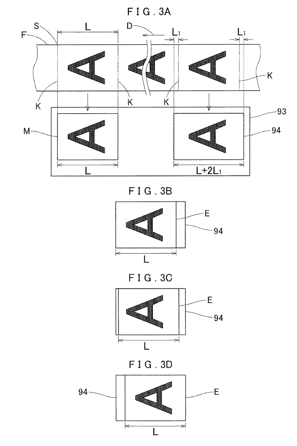
[0030]A bag making machine 1 according to the first embodiment shown in FIG. 1 is configured to manufacture bags from an elongated film F having on its one surface print patterns repeatedly printed at a print pitch corresponding to a predetermined number of bags (one bag in this case). The bag making machine 1 performs sealing, cooling, and cutting with respect to a film F for each length corresponding to a predetermined number of bags (one bag in this case). Assume that in the following description, the length of the film F or a bag indicates the length along the lengthwise direction of the film F unless otherwise specified. The bag making machine 1 includes a feeding mechanism 2, a transverse sealing device 4, as a processing unit U, a moving mechanism 48, a cooling device 5, a shooting device 6, a cutter 8, and a computer 9.

[0031]The feeding mechanism 2 feeds the film F in its lengthwise direction, and includes a feed shaft 21, a turn bar 22, a slit blade 23, a...

second embodiment

2. Second Embodiment

[0068]A bag making machine 1A according to the second embodiment shown in FIG. 7 includes, in addition to the components of the bag making machine 1, an automatic adjusting means 100 for automatically adjusting the position to perform processing (sealing, cooling, or cutting in this case) with respect to a film F, the tension of the film F, and the feed amount of the film F on the basis of detection results obtained by an image processing device 91, and also includes a motor 46 that causes a pinion 43 to pivot and a motor 56 that causes a pinion 53 to pivot. Note that the same reference characters denote the same members throughout the bag making machine 1 according to the first embodiment and the bag making machine 1A according to the second embodiment, and a description of the members will be omitted unless otherwise specified.

[0069]As shown in FIG. 8, the automatic adjusting means 100 includes a motor control unit 47, a feed amount control unit 31, a pressure ...

third embodiment

3. Third Embodiment

[0078]A bag making machine 1B according to the third embodiment shown in FIG. 9 is configured to perform processes such as sealing and cutting while performing continuous feeding instead of intermittent feeding. The feed amount in the case of continuous feeding corresponds to the length of a bag as a product (i.e., a product length). Note that the same reference characters denote the same members throughout the bag making machine 1 according to the first embodiment and the bag making machine 1B according to the third embodiment, and a description of the members will be omitted unless otherwise specified.

[0079]In the bag making machine 1B, a dancer roller 25 does not serve to change continuous feeding to intermittent feeding but serves to apply tension to each of base material films F1 and F2, i.e., a film F. A transverse sealing device 4B includes an upper seal roller 41B and a lower seal roller 42B that are arranged with their pivot shafts extending along the wid...


PUM


Abstract

A bag making machine for manufacturing bags from an elongated film having print patterns repeatedly printed on one surface or two surfaces at a print pitch corresponding to a predetermined number of bags includes a processing unit configured to process the film for each length corresponding to the predetermined number of bags, a moving mechanism configured to move the processing unit, a shooting device, and an image processing device. The shooting device includes not less than one line sensor installed with a longitudinal direction of the line sensor extending along the widthwise direction of the film and obtains a linear image extending throughout a width of the film for each shooting operation. The image processing device sequentially receives the linear images from the shooting device and detects the actual length of the predetermined number of bags of the film based on an image extending throughout the width of the film.

Description

BACKGROUND OF THE INVENTION1. Field of the Invention[0001]The present invention relates to a bag making machine.2. Description of Related Art[0002]When a bag making machine makes bags from a film, expansion and contraction sometimes occur in the film due to the tension of the feed rollers, the heat generated in a heat seal process, and subsequent cooling, and the bag pitch sometimes changes. In such a case, when bags are made by sealing and cutting a film at initially set positions, sealing and cutting may not be performed at positions matching print patterns on the film, resulting in defective products. For this reason, conventionally, visual inspections by operators have been made to ascertain whether a sealing position and a cutting position are correct. However, visual inspections by operators lead to low work efficiency.[0003]In order to solve such a problem, the bag making apparatus disclosed in JP No. 2003-33981 A is configured to shoot a print design on a film with a CCD cam...

Claims


Application Information

Patent Timeline
Patent Type & Authority Applications(United States)
IPC IPC(8): B31B70/00B31B70/64B31B70/10B31B70/16B31B70/88
CPCB31B70/006B31B70/645B31B70/10B31B70/16B31B70/88B31B2155/001B31B2160/20
Inventor YANAGISAWA, SHINJITAKAMATSU, HIROSHIYAMAO, MASAYUKIHIBINO, MINORUKANEKO, NAOKIHIKAMI, YOSHITAKATAMADA, ATSUTOOKAMOTO, HIROMITAKAGI, SEIJI
Owner NEW IWASHO CO LTD
Why Eureka
Try Eureka