Method for operating a piston pump, control device of a piston pump, and piston pump

a technology of control device and piston pump, which is applied in the direction of positive displacement liquid engine, electric control, semiconductor device, etc., can solve the problems of short circuit, short circuit, and small amount of energy drawn from the coil, and achieve the effect of sharp piston movement and short circui

Active Publication Date: 2018-11-29
ROBERT BOSCH GMBH
View PDF0 Cites 0 Cited by
  • Summary
  • Abstract
  • Description
  • Claims
  • Application Information

AI Technical Summary

Benefits of technology

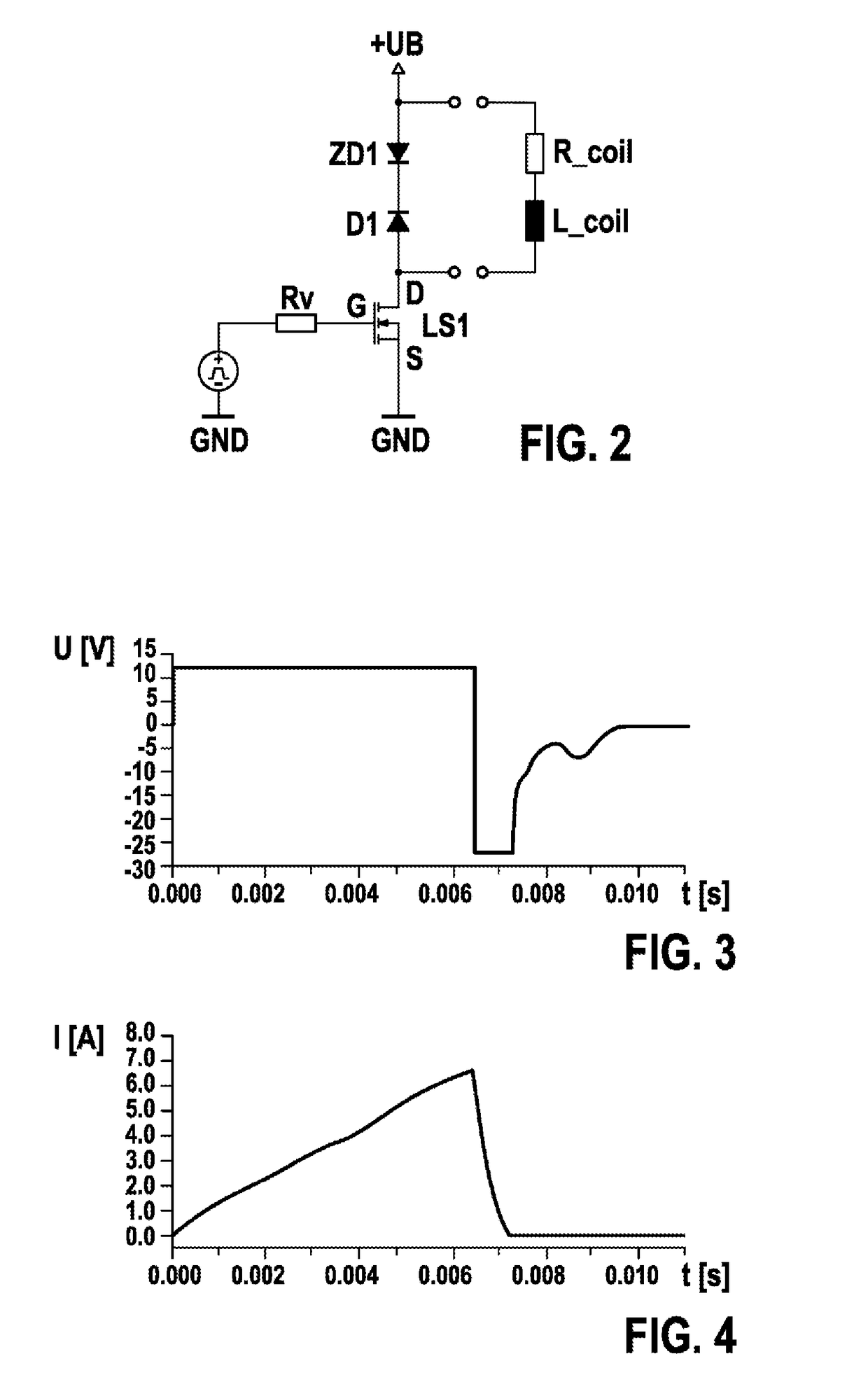
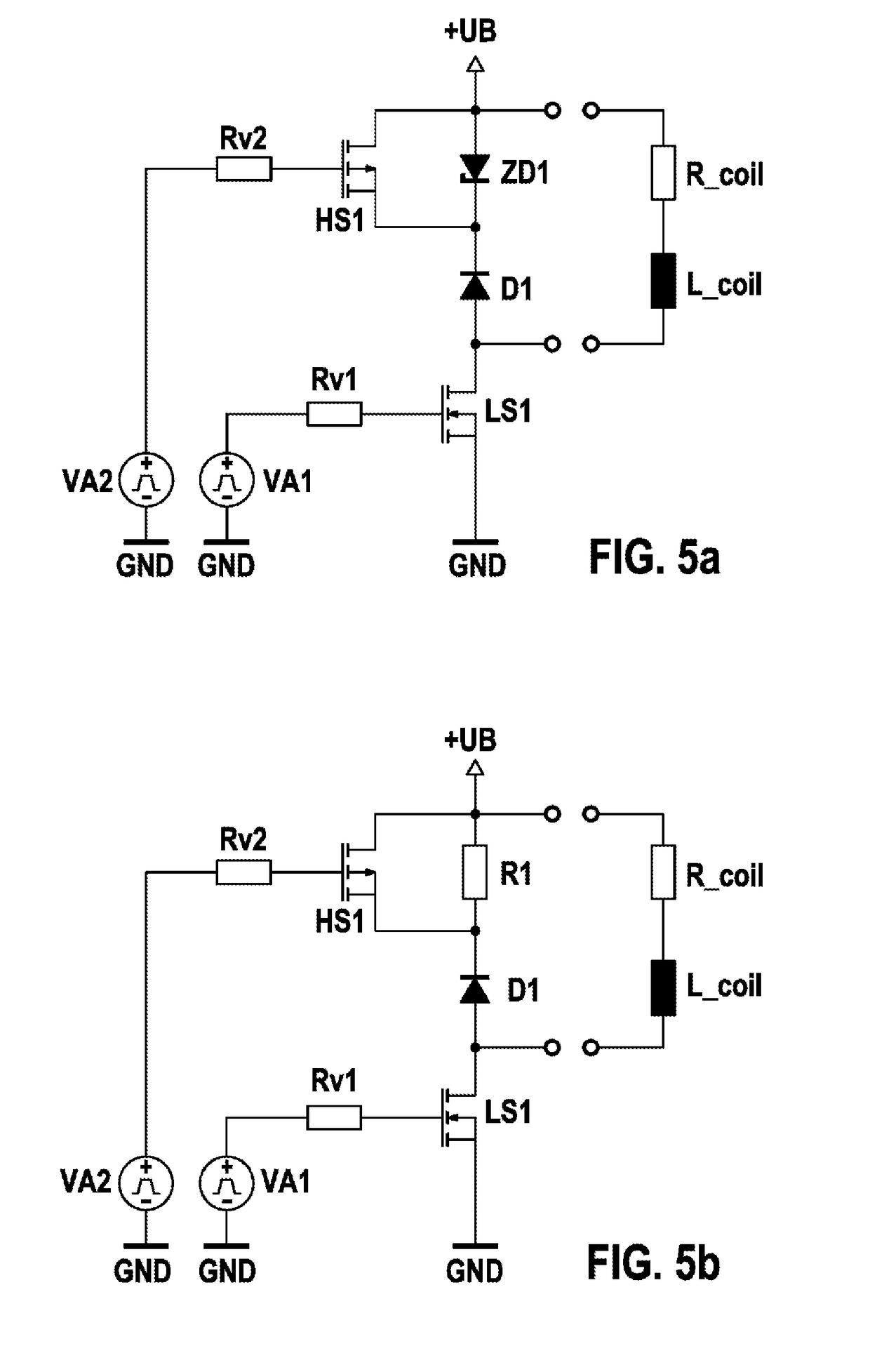
[0005]In order to overcome the abovementioned disadvantages, it is proposed, according to the invention, to use two different quenching methods for the current in the coil. A second quenching method consi

Problems solved by technology

However, only a small amount of energy can be drawn from the coil when there is a short circuit or a very high resistance.
One disadvantage of this solution is that the current is abruptly quenched and the piston therefore remains in a sharply deflected position for only a short time.
On account of the inertia of the hydraulic system, this time period may not be

Method used


Image

  • Method for operating a piston pump, control device of a piston pump, and piston pump
  • Method for operating a piston pump, control device of a piston pump, and piston pump
  • Method for operating a piston pump, control device of a piston pump, and piston pump

Examples


fifth embodiment

[0052]FIG. 8a shows the invention in the form of a drive circuit which can feed coil current back to a current supply device which supplies the drive circuit with the supply voltage +UB. In terms of the basic design, the drive circuit is an H bridge circuit. In the branch of the bridge illustrated on the left-hand side in FIG. 8a, there is a semiconductor switch HS1 on the side of the supply voltage +UB. A conventional reverse-biased diode D2 is connected in series with said semiconductor switch in the left-hand branch. The right-hand branch of the H bridge is of similar design to the left-hand branch, but the diode D1, which is likewise reverse-biased with respect to the supply voltage +UB, is connected to the supply voltage +UB. However, the semiconductor switch LS1 is connected to ground. Therefore, the semiconductor switch HS1 and the diode D1 are interconnected at the supply voltage +UB, while the diode D2 and the semiconductor switch LS1 are interconnected at ground GND. The c...

fourth embodiment

[0053]FIG. 8b shows the invention in the form of a drive circuit. The drive circuit is designed as an H bridge, wherein the two branches of the H bridge each have two semiconductor switches, specifically HS1 and LS1 in the left-hand branch, and HS2 and LS2 in the right-hand branch. The coil L_coil, together with its internal resistance R_coil, is connected between the voltage divider points between the semiconductor switches HS1 and LS1 and, respectively, HS2 and LS2. The coil can be removable from the circuit, for example by means of plug contacts. The H bridge is connected between a supply voltage +UB and ground GND. A conventional diode D1, D2, D3 and, respectively, D4 is connected in parallel with each of the semiconductor switches HS1, HS2, LS1 and LS2, wherein the diodes are connected to the source and drain in each case. The diodes are reverse-biased with respect to the supply voltage +UB. In a switch-on mode, either the semiconductor switches HS1 and LS2 or the semiconductor...


PUM


Abstract

The invention relates to a method for operating a piston pump, which is driven by means of a coil (1) of an electromagnet, wherein a piston (2) of the piston pump can be moved against a restoring force by means of the electromagnet, wherein a voltage (U) is applied to the coil (1) during a switch-on duration such that a current (I) flows through the coil (1) and the piston (2) is accelerated, wherein two different quenching methods are used for the current (I) in the coil (1).

Description

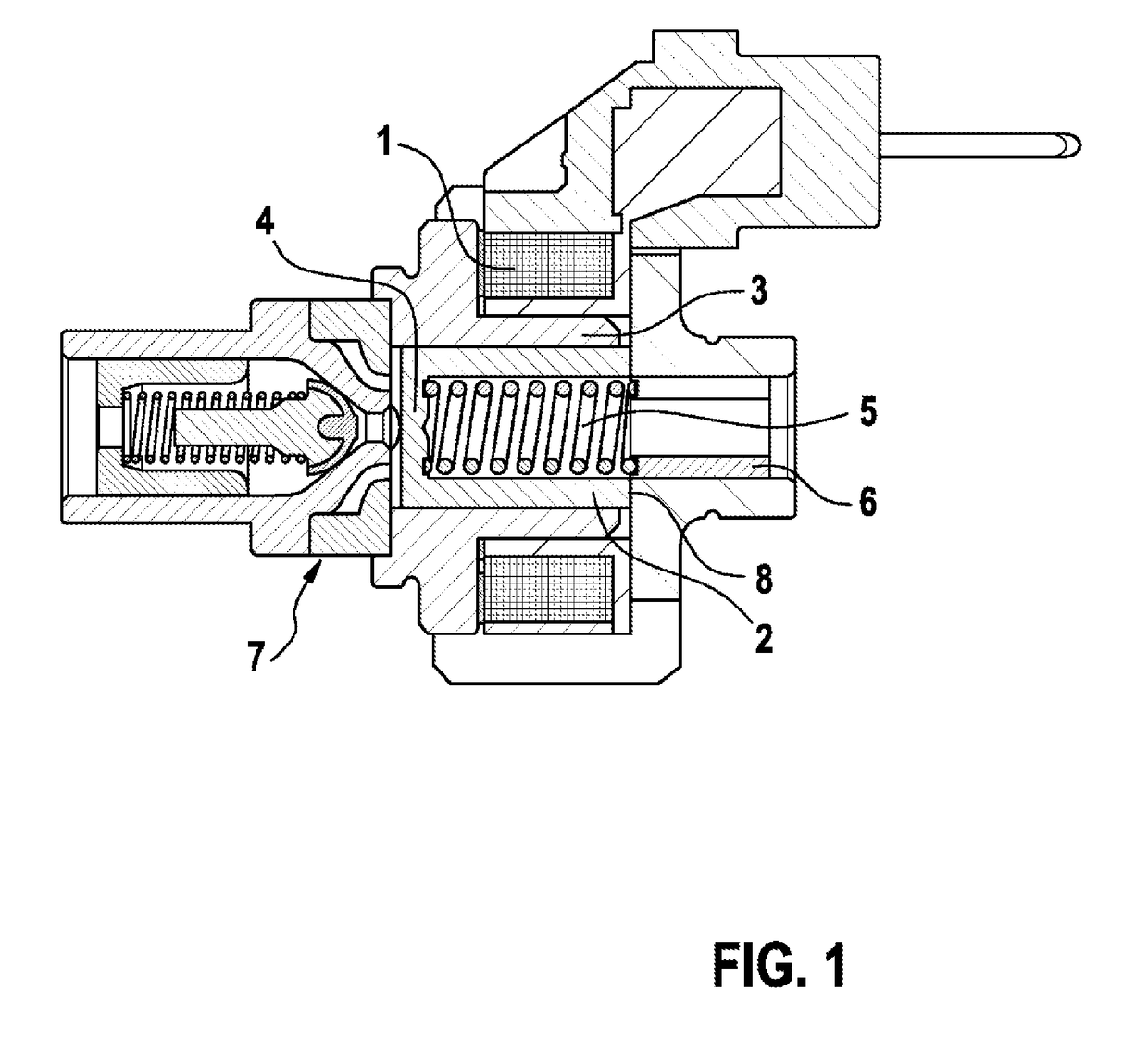
BACKGROUND OF THE INVENTION[0001]The present invention relates to a method for operating a piston pump which is driven by means of a coil of an electromagnet, wherein a piston of the piston pump can be moved against a restoring force by means of the electromagnet. During a switch-on period, a voltage is applied to the coil, so that said voltage drives a current through the coil. The coil produces magnetic forces and accelerates the piston. The invention further relates to a drive device for the piston pump, and to a piston pump comprising a drive device.[0002]Piston pumps which can be driven by means of the coil of an electromagnet are known from the prior art. Said piston pumps can be used, for example, as fuel pumps. By way of example, one embodiment of a pump of this type as a lifting armature pump is illustrated in FIG. 1. The piston pump comprises a coil 1, a piston 2 having a piston head 4, a cylinder 3, a helical spring 5 having an abutment 6 and a valve unit 7. When a curren...

Claims


Application Information

Patent Timeline
IPC IPC(8): F04B17/04F02D41/20H01L29/866
CPCF04B17/044F02D41/20H01L29/866F02D2041/2034F02D2041/2041F02D2041/2051F04B17/042
Inventor NITSCHE, FRANKALLGEIER, THORSTENMAEURER, WALTER
Owner ROBERT BOSCH GMBH
Why Eureka
Try Eureka