

Multi-stage batch polishing method for end surface of optical fiber connector, and polishing film
a technology of optical fiber connectors and polishing films, applied in the direction of grinding drives, flexible parts wheels, manufacturing tools, etc., can solve the problems of increased costs and installation space, high labor intensity, and long time-consuming work, so as to improve the polishing process and eliminate the complexity of placing polishing films. , the effect of high precision
- Summary
- Abstract
- Description
- Claims
- Application Information
AI Technical Summary
Benefits of technology
Problems solved by technology
Method used
Image

Examples
example 1
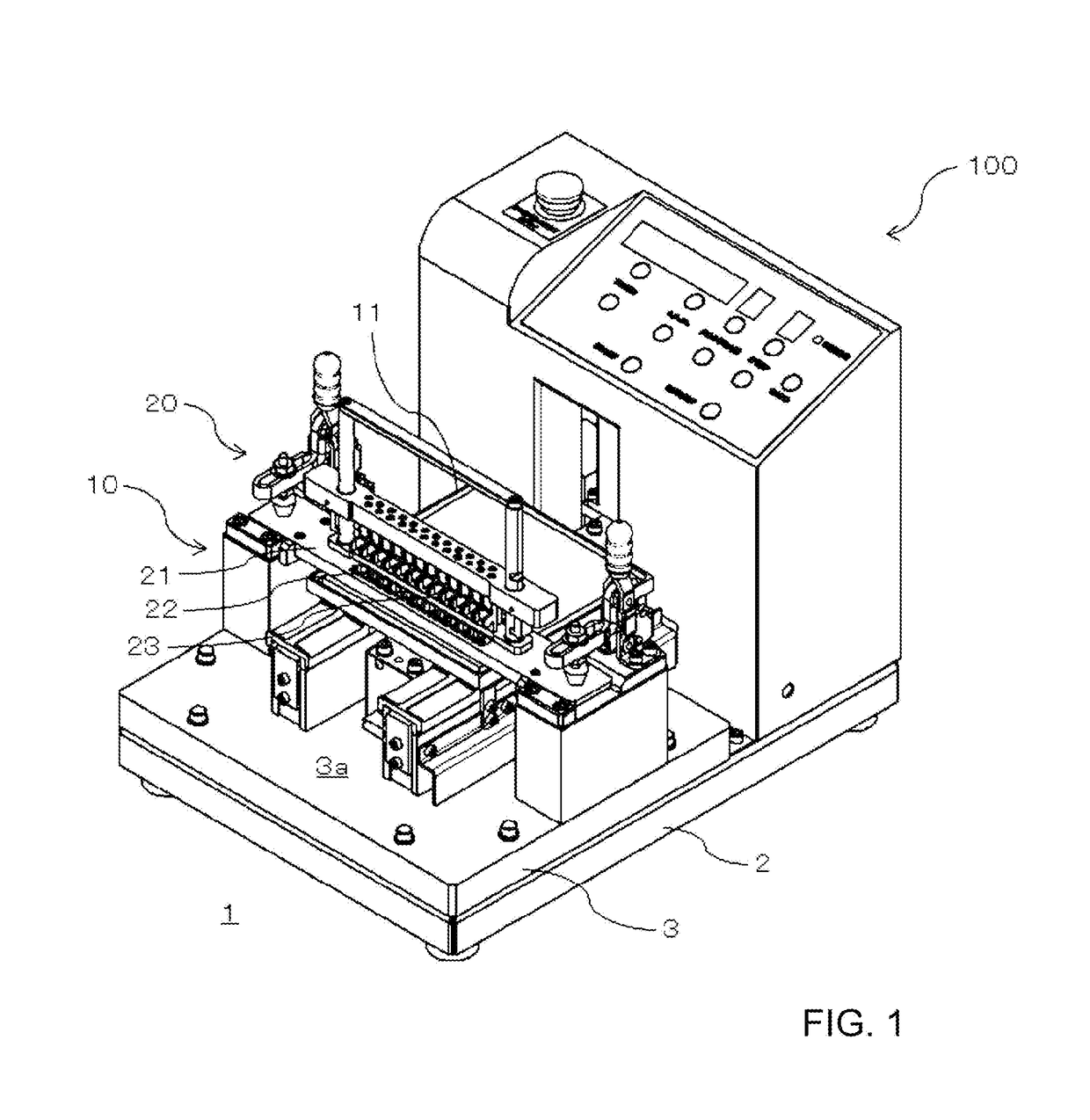
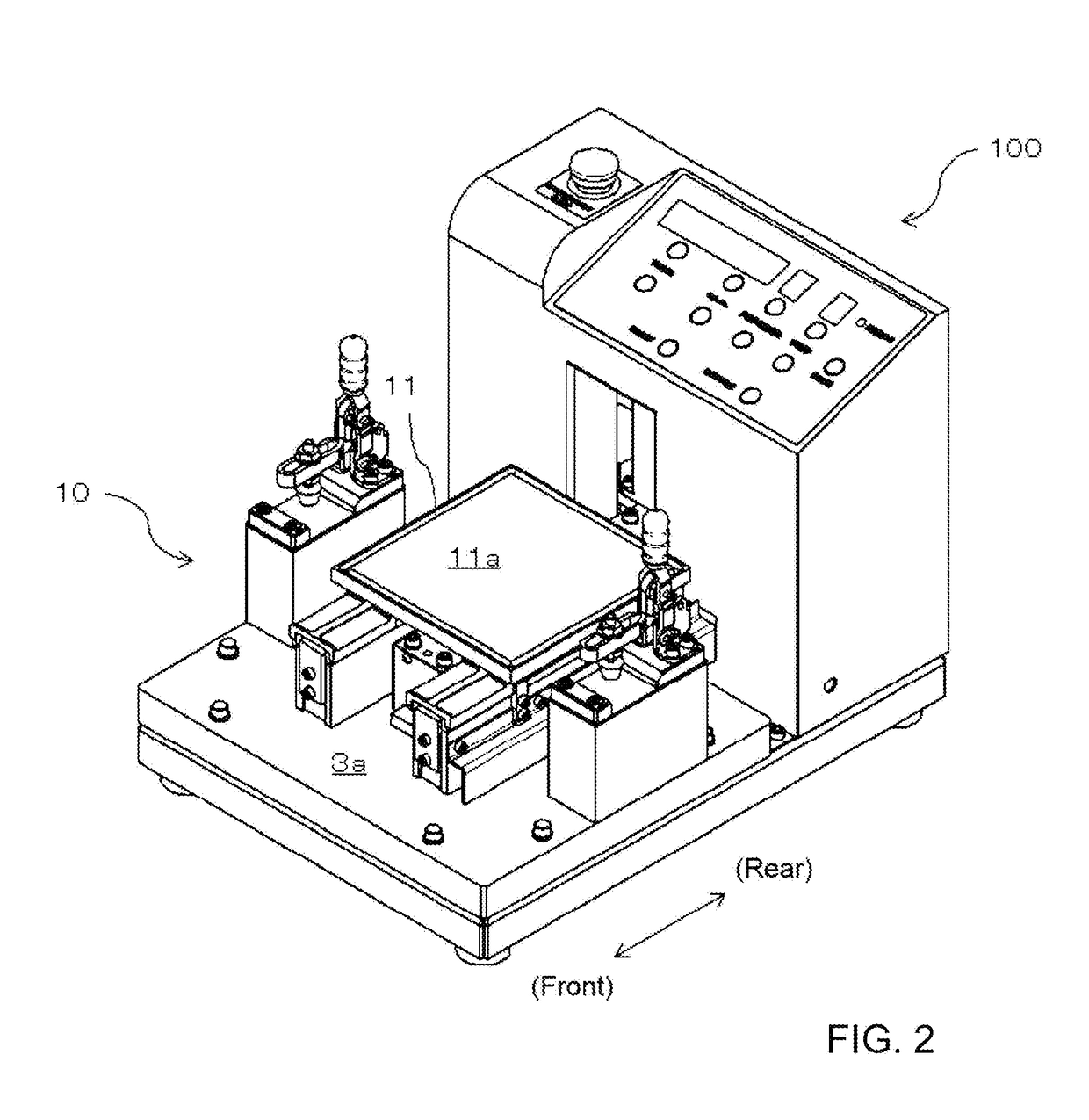
(1) Conditions of the Polishing Apparatus
[0109]Size of the placement surface of the polishing plate (H×H′) 145 mm×145 mm
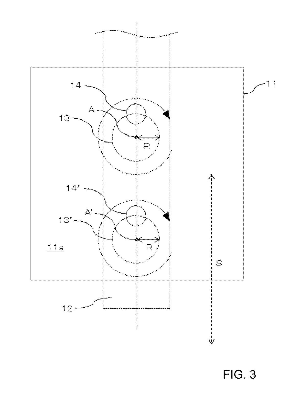
Diameter of circular motion of the polishing plate (D) 15 mm
Linear movement distance of the polishing plate (S) 86 mm
Moving speed in a straight line of the polishing plate (V1) 86 mm / 5 min
Rotational speed of the polishing plate (V2) 270 rpm
Water for polishing distilled water
(2) Conditions of Polishing Film
[0110]Polishing surface for rough polishing
[0111]Polishing film containing aluminum oxide abrasive grains having an average grain size of 9 μm
Polishing surface for intermediate polishing
[0112]Polishing film containing diamond abrasive grains having an average grain size of 1 μm
Polished surface for finish polishing
[0113]Polishing film containing silica particles having an average particle size of 20 to 30 nm
Cleaning Surface
[0114]Flocked film obtained by flocking nylon fiber (1 denier) having a length of 0.4 mm on a PET film
Longitudinal width of the cleaning surface...
example 2
(1) Conditions of the Polishing Apparatus
Same as in Example 1
(2) Conditions of the Polishing Film
[0117]Same as in Example 1 for the polishing surface and the cleaning surface Longitudinal width of the cleaning surface (Lc≥R) 9 mm
Groove width (Lg) 0.5 mm
Polishing time ratio configuration
[0118]Rough polishing:intermediate polishing:finish polishing=1:1.5:1.1
(3) Determined Dimensions of the Polishing Film
[0119]L4′=10 (mm), L5′=15 mm, L3′=11 mm
L4=25 mm, L5=30 (mm), L6=70 mm
example 3
(1) Conditions of the Polishing Apparatus
[0120]Linear movement distance of the polishing plate (S) 96 mm
The other conditions are the same as in Example 1.
(2) Conditions of the Polishing Film
[0121]Same as in Example 1 for the polishing surface and the cleaning surface
Longitudinal width of the cleaning surface (Lc=D) 15 mm
Groove width (Lg) About 0 mm
Polishing time ratio configuration
[0122]Rough polishing:intermediate polishing:finish polishing=1:1.5:1.1
(3) Determined Dimensions of the Polishing Film
[0123]L7′=10 (mm), L8′=15 mm, L9′=11 mm
L7=25 mm, L8=30 (mm), L9=60 mm
PUM
 Abstract
Description
Claims
Application Information