Steel, carburized steel component, and method for manufacturing carburized steel component

a carburized steel and component technology, applied in the direction of manufacturing tools, furnaces, heat treatment equipment, etc., can solve the problems of high cost of cutting related to the cost of manufacturing carburized steel components, increased contact pressure on forming tools, and disadvantageous cutting, etc., to achieve excellent cold forgeability, high critical compression ratio, and small deformation resistance

Inactive Publication Date: 2018-12-06
NIPPON STEEL CORP
View PDF0 Cites 4 Cited by
  • Summary
  • Abstract
  • Description
  • Claims
  • Application Information

AI Technical Summary

Benefits of technology

[0022]In the steel according to the present invention, the steel has excellent cold forgeability due to small deformation resistance and a high critical compression ratio at the time of cold forging compared to a steel in the related art, coarse grains are not formed therein during carburizing, and ...

Problems solved by technology

Cutting related cost is very high in the cost of manufacturing carburized steel components.
Due to not only expensive cutting tools but also a large amount of generated cutting chips, cutting is disadvantageous even from a viewpoint of a yield.
However, in replacing cutting with warm forging or cold forging, when a steel for carburizing has significant deformation resistance, contact pressure applied to a forming tool increases, so...

Method used

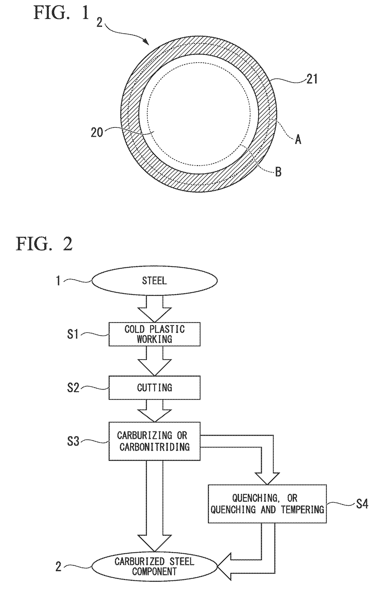

Image

  • Steel, carburized steel component, and method for manufacturing carburized steel component

Examples


example 1

[0162]Steels a to aa having the chemical compositions shown in Table 1A and Table 1B were melted and made into ingots using a converter (270 ton), continuous casting was executed using a continuous casting machine, and slabs of 220×220 mm square were manufactured. Here, super-heating of a molten steel inside a tundish was set to 30° C., and the casting speed was set to 1.0 m / min.

[0163]In continuous casting of the slabs, the average cooling rate within the temperature range from the liquidus temperature to the solidus temperature at a position in the depth of 15 mm from a surface of a slab was controlled by changing the quantity of cooling water of a mold. In this manner, slabs a to aa which had the chemical compositions shown in Table 1A and Table 1B were continuously cast. In slab o, slab p, and slab q, the primary arm spacing of dendrite within the range of 15 mm from the surface layer was 600 μm or longer. In other slabs, the primary arm spacing of dendrite within the range of 15...

example 2

[0208]Under the same manufacturing conditions as the steel a and the steel g except for the average cooling rate (hereinafter, will be referred to as the “average cooling rate”) within the temperature range from the liquidus temperature to the solidus temperature at a position in the depth of 15 mm from a surface of the slab, steels for carburizing having the same chemical composition as that of the steel a or the steel g were manufactured, and various evaluations were carried out with respect to these steels for carburizing by the same method as that of the steel a and the steel g. The average cooling rates followed the values shown in Table 3.

TABLE 3Evaluation result of steel for carburizingCriticalAverageHardnesscompressionPresenceDistanceWear amount ofcooling(Hv)ratio (%)densitybetweenflank (mm)TestrateBefore SAAfter SABefore SAAfter SAof sulfideSulfidesBefore SANo.Steel(° C. / min)processprocessprocessprocess(pieces / mm2)(μm)process1a3001191056869  349 23.6 0.121-2a5501151056970* ...


PUM

PropertyMeasurementUnit
Lengthaaaaaaaaaa
Lengthaaaaaaaaaa
Lengthaaaaaaaaaa

Abstract

A steel according to an aspect of the present invention has a chemical composition within a predetermined range, in which a hardenability index Ceq ranges from greater than 7.5 to smaller than 44.0, an AlN precipitation index IAlN ranges from greater than 0.00030 to smaller than 0.00110, a metallographic structure includes ferrite ranging from 85 to 100 area %, an average distance between sulfides, which are observed in a cross section parallel to a rolling direction of the steel and have an equivalent circle diameter ranging from 1 μm or greater to smaller than 2 μm, is shorter than 30.0 μm, and a presence density of the sulfides, which are observed in the cross section parallel to the rolling direction of the steel and have an equivalent circle diameter ranging from 1 μm or greater to smaller than 2 μm, is 300 pieces/mm2 or more.

Description

TECHNICAL FIELD OF THE INVENTION[0001]The present invention relates to a steel, a carburized steel component, and a method for manufacturing a carburized steel component.[0002]Priority is claimed on Japanese Patent Application No. 2015-232118, filed on Nov. 27, 2015, the content of which is incorporated herein by reference.RELATED ART[0003]Generally, Mn, Cr, Mo, Ni, and the like are added in a combination to steels used for components for machine structural use. A steel for carburizing having such a chemical composition and being manufactured via processes such as casting, forging, and rolling is subjected to machining such as forging and cutting, and is then subjected to heat treatment such as carburizing. Accordingly, it is possible to obtain a carburized steel component including a carburized layer that is a hard layer in a surface layer area, and a steel portion that is a base metal which has not been affected by carburizing treatment.[0004]Cutting related cost is very high in t...

Claims


Application Information

Patent Timeline
IPC IPC(8): C23C8/22C23C8/32C23C8/80C21D9/32C21D9/28C21D8/00C21D1/06C22C38/54C22C38/28C22C38/26C22C38/24C22C38/22C22C38/20C22C38/06C22C38/04C22C38/02C22C38/00
CPCC23C8/22C23C8/32C23C8/80C21D9/32C21D9/28C21D8/005C21D1/06C22C38/54C22C38/28C22C38/26C22C38/24C22C38/22C22C38/20C22C38/06C22C38/04C22C38/02C22C38/005C22C38/002C22C38/001C22C38/00C22C38/60C21D8/065C21D2211/004C21D2211/005C21D8/06C22C38/32
Inventor SHIGA, AKIRAHASEGAWA, HAJIMEKUBOTA, MANABUMIZUKAMI, HIDEO
Owner NIPPON STEEL CORP
Why Eureka
Try Eureka