Optical measurement apparatus and optical measurement method

a measurement apparatus and optical technology, applied in the direction of liquid/fluent solid measurement, instruments, material analysis, etc., can solve the problem of inability to accurately measure the thickness of each layer of a sample in which a plurality of layers are stacked, and the inability to meet the need for quick measurement of in-plane film thickness distribution, etc. problem, to achieve the effect of high speed and higher accuracy

Active Publication Date: 2018-12-06
OTSUKA DENSHI CO LTD
View PDF0 Cites 1 Cited by
  • Summary
  • Abstract
  • Description
  • Claims
  • Application Information

AI Technical Summary

Benefits of technology

[0006]One object of the present technical concept is to provide an optical measurement apparatus and an optical measurement method capable of measuring an in-plane film thickness distribution of various samples at a higher speed and with higher accuracy. Ano

Problems solved by technology

The configurations disclosed in Japanese Patent Laying-Open No. 2009-092454 and Japanese Patent Laying-Open No. 2013-079921 are basically directed to measurement by irradiation with light to one certain point of a sample, and they are unable to sufficiently meet the need for quick measurement of an in-plane film thickness distribution.
With the peak-valley method, a film thickness may not accurately be measured under the i

Method used


Image

  • Optical measurement apparatus and optical measurement method
  • Optical measurement apparatus and optical measurement method
  • Optical measurement apparatus and optical measurement method

Examples


application examples

G. Application Examples

[0313]Application examples of the optical measurement apparatus according to the present embodiment will now be described.

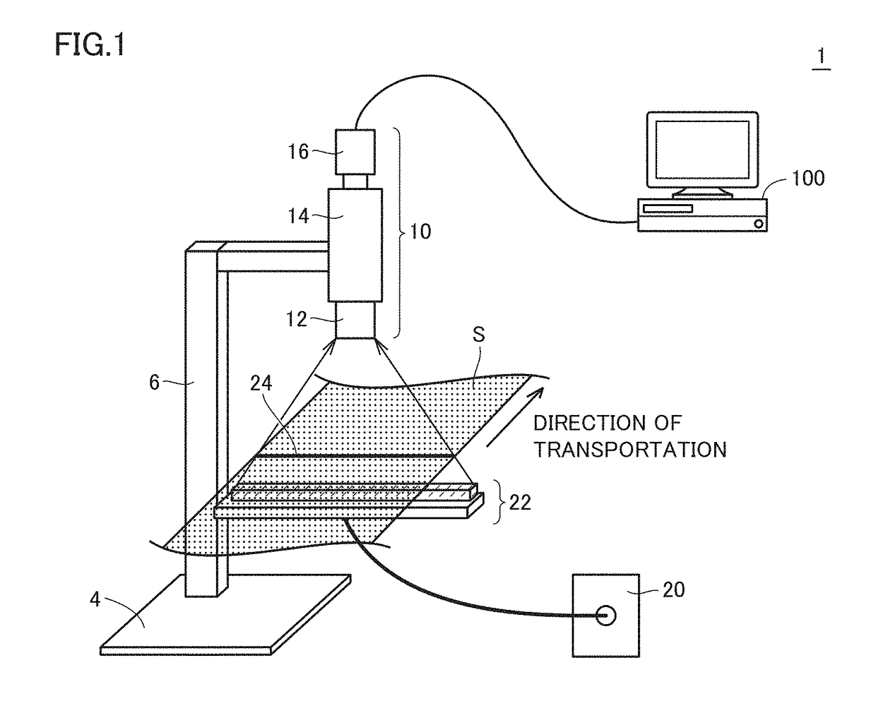
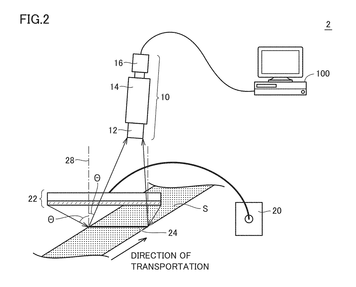
[0314]For example, by being arranged in a film manufacturing line, the optical measurement apparatus according to the present embodiment can conduct in-line measurement of a film thickness. The optical measurement apparatus according to the present embodiment can output an in-plane film thickness distribution (that is, a two-dimensional film thickness distribution) of a sample. For example, a defective portion which may be produced in the film manufacturing line can also be specified based on variation in film thickness trend in a direction of transportation, that is, a machine direction (MD), of the sample.

[0315]More specifically, for example, the film manufacturing line includes a plurality of transportation rollers and any transportation roller contains a defective portion such as formation of a projecting portion in the film or introduc...


PUM


Abstract

An optical measurement apparatus includes an irradiation optical system which linearly irradiates a measurement target with measurement light having a certain wavelength range, a measurement optical system which receives linear measurement interference light which is transmitted light or reflected light originating from the measurement target as a result of irradiation with the measurement light, and a processing device. The processing device includes a first calculation module that calculates a modification factor depending on with an angle of incidence on the measurement optical system from each measurement point in association with a region in the two-dimensional image corresponding to each measurement point in the measurement target irradiated with the measurement light and a second calculation module that calculates optical characteristics of the measurement target by applying the corresponding modification factor to a value for each pixel included in the two-dimensional image.

Description

BACKGROUND OF THE INVENTIONField of the Invention[0001]The present technical concept relates to an optical measurement apparatus and an optical measurement method capable of measuring optical characteristics such as a film thickness and a refractive index.Description of the Background Art[0002]A technique to measure a film thickness of a sample such as a functional resin film or a semiconductor substrate has been known. For example, Japanese Patent Laying-Open No. 2009-092454 discloses a multi-layered film analysis apparatus and a multi-layered film analysis method capable of highly accurately measuring a film thickness of a multi-layered film sample having wavelength-dependency. Japanese Patent Laying-Open No. 2013-079921 discloses a film thickness measurement apparatus and a film thickness measurement method capable of accurately measuring a thickness of a dielectric thin film of which refractive index is not known.[0003]In general, a sample to be subjected to measurement has a ce...

Claims


Application Information

Patent Timeline
IPC IPC(8): G01B11/06G01B9/02
CPCG01B11/06G01B9/02043G01B9/02024G01B11/0675G01N21/453G01N21/45G01N2021/458G01B11/0625G01N21/8422G01B9/02G01D18/002G06F17/14G01N21/41G01B9/02041G01N21/00
Inventor INOUE, NOBUYUKITAGUCHI, KUNIKAZU
Owner OTSUKA DENSHI CO LTD
Why Eureka
Try Eureka