Multi-transformer llc resonant converter circuit

a resonant converter and multi-transformer technology, applied in the direction of electric variable regulation, process and machine control, instruments, etc., can solve the problems of increasing the volume of the converter, limiting the operation of higher frequency, and most losses in the llc converter, so as to reduce the size of the transformer, reduce the ripple of input-capacitor current, and reduce the forward voltage drop

Active Publication Date: 2018-12-06
MURATA MFG CO LTD
View PDF11 Cites 15 Cited by
  • Summary
  • Abstract
  • Description
  • Claims
  • Application Information

AI Technical Summary

Benefits of technology

[0007]The primary windings of the transformers and the freewheeling diodes that connect the primary windings provide separate paths that allow the magnetizing-inductance-current energy stored in the transformers during a previous cycle to be transferred back to the DC input. This allows the size of the transformer to be reduced due to ripple-current cancellation and magnetic-flux cancellation. As a result, magnetic core losses, input-capacitor current ripple, and MOSFET losses are reduced by eliminating losses from the MOSFET body diodes. Schottky diodes or ultrafast recovery diodes that have lower forward voltage drops than the MOSFET body diodes (which can be approximately 2 V) can be used. Also, losses in the synchronous rectifier MOSFETs are reduced because ZCS is used before terminating the synchronous rectifier MOSFET cycle. A conventional feedback loop can be used to control the synchronous rectifier MOSFET cycle depending on load and input voltage. As a result, the LLC converter efficiency is improved, even if the LLC converter is operated below the resonant frequency. Due to magnetic-flux cancellation, the volume of the transformer is reduced in high-current-load applications, allowing for a reduction in conduction losses of the secondary winding and core losses of each transformer.

Problems solved by technology

In high-power and high-load-current applications, most losses in an LLC converter come from synchronous rectifiers, transformer cores, conductive windings, and body diodes of the metal-oxide-semiconductor field-effect transistors (MOSFETs).
For high-frequency LLC converter operation, magnetic-core loss limits higher frequency operation and increases converter volume.
However, Cohen's converter has a disadvantage in that the transformer working conditions are the same as in previous conventional LLC converter circuits in that the transformer must store a significant amount of energy.
These design constraints require a large transformer core that results in high conductive losses in the transformer.
Also, the losses from the synchronous-rectifiers MOSFETs are high.
This non-zero-current switching (non-ZCS) reduces LLC converter efficiency when operating at frequencies below the resonant frequency.
When the switching frequency is above the resonant frequency, the resonant half cycle is not completed and interrupted by the start of the other half of the switching cycle, which results in the power switches having increased turn off losses and in the secondary-side rectifiers having higher switching losses.

Method used


Image

  • Multi-transformer llc resonant converter circuit
  • Multi-transformer llc resonant converter circuit
  • Multi-transformer llc resonant converter circuit

Examples


Embodiment Construction

[0019]It should be understood that the foregoing description is only illustrative of the present invention. Various alternatives and modifications can be devised by those skilled in the art without departing from the present invention. Accordingly, the present invention is intended to embrace all such alternatives, modifications, and variances that fall within the scope of the appended claims.

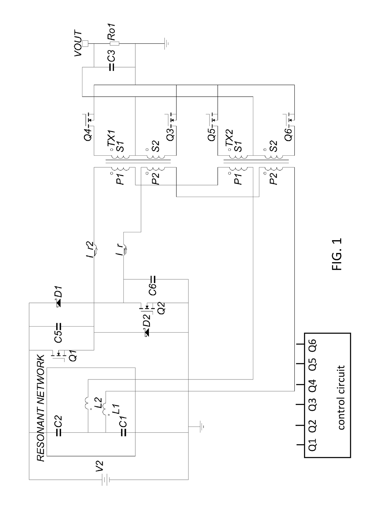
[0020]The LLC converter of FIG. 1 reduces transformer size, transformer-core losses, synchronous-rectifier MOSFET losses, and MOSFET-body-diode conduction losses. The LLC converter of FIG. 1 equally distributes current to the synchronous-rectifier MOSFETs, while the two transformers have the same magnetizing and primary currents. As a result, the load current in each secondary side of the two transformers matches or is substantially the same.

[0021]As shown in FIG. 1, the LLC converter includes an input voltage V2; a resonant circuit including inductors L1, L2 and capacitors C1, C2; power switch...


PUM


Abstract

An LLC converter includes a resonant circuit connected to a DC input voltage, a switching circuit connected to the DC input voltage, transformers each including primary windings and secondary windings, and synchronous rectifiers each connected to one secondary winding and to ground. The primary windings of the transformers include a first primary winding and a second primary winding. The first primary windings of the transformers are connected in series, and the second primary windings of each of the plurality of transformers are connected in series. The series-connected first primary windings and the series-connected second primary windings are directly connected in parallel with the resonant circuit. A first current from a first switch flows into the series-connected first primary windings, and a second current from a second switch flows into the series-connected second primary windings. Currents from each of the secondary windings are equal or substantially equal.

Description

BACKGROUND OF THE INVENTION1. Field of the Invention[0001]The present invention relates to power converters. More specifically, the present invention relates to a multi-transformer resonant DC-DC converter circuit, e.g., an LLC converter including two inductors and a capacitor that reduce transformer core losses.2. Description of the Related Art[0002]In high-power and high-load-current applications, most losses in an LLC converter come from synchronous rectifiers, transformer cores, conductive windings, and body diodes of the metal-oxide-semiconductor field-effect transistors (MOSFETs). To achieve higher efficiency, LLC resonant converters are designed to operate with zero-voltage switching (ZVS) that requires a large magnetizing current. Therefore, the peak current of the LLC converter is higher than a hard-switching converter.[0003]Improved switching devices, such as gallium nitride (GAN) devices, and new magnetic materials allow for a significant increase in switching frequency. ...

Claims


Application Information

Patent Timeline
Patent Type & Authority Applications(United States)
IPC IPC(8): H02M3/335H02M1/34
CPCH02M3/33592H02M1/34H02M2001/0054H02M1/14Y02B70/10Y02P80/10H02M1/0048H02M1/0058H02M7/4826H02M1/0054H02M7/4811H02M7/4815
Inventor KAKALASHVILI, NANA
Owner MURATA MFG CO LTD
Why Eureka
Try Eureka