Battery including thermal insulation

a battery and thermal insulation technology, applied in the field of batteries, can solve the problems of radiation loss present is potential and undesirable heat leakage, and affecting battery performance and self-discharge, so as to reduce energy loss during battery downtime, increase battery self-sufficiency, and cost-effective

Active Publication Date: 2018-12-13
ROBERT BOSCH GMBH
View PDF2 Cites 2 Cited by
  • Summary
  • Abstract
  • Description
  • Claims
  • Application Information

AI Technical Summary

Benefits of technology

[0006]An object of the present invention is to at least partially eliminate the above-described disadvantages. In particular, the object of the present invention is to greatly reduce the energy losses during downtimes of the battery and, therefore, to increase the self-sufficiency of the battery in a cost-effective and energy-saving way. Within the scope of the present invention, “self-sufficiency of the battery” is to be understood to mean a type of thermal insulation system for the thermal management of the battery. In this case, the battery does not require a connection to the grid, but rather utilizes the available energy of the battery for the thermal management, so that the battery is brought to the optimal operating temperature or is held there.

Problems solved by technology

Such battery concepts may need to be heated during operation or during start-up, but they potentially require no cooling capacity or only very little cooling capacity for this purpose during operation.
In this case, connection lines, mechanical supports, and other thermal bridges as well as the radiation losses which are present are potential and undesirable heat leaks.
These thermal power losses negatively affect the battery performance and self-discharge, which usually must be rectified with the aid of supplied energy.
This costs energy and may discharge the battery.
A battery which has cooled down, i.e., which is at room temperature, is mostly incapable of heating itself up, since the kinetics of the cell reaction and the internal power processes are still too limited.
The disadvantage of the conventional approaches is the absence of the possibility for holding the battery at operating temperature during standing phases and for thereby dispensing with an external energy source for the thermal activation of the battery.
The related art therefore lacks an approach for the energy-saving thermal management or thermal activation of the battery, the self-sufficiency of the batteries, in particular, being increased and, therefore, longer standing phases of the vehicles being made possible.

Method used


Image

  • Battery including thermal insulation

Examples


Embodiment Construction

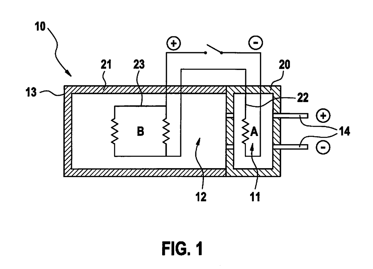
[0022]FIG. 1 schematically shows a battery 10 according to the present invention, which includes a battery housing 13 in which first battery module 11 and second battery module 12 are situated. Battery contacts 14 are situated on the shared battery housing, which are used for connecting the battery to a vehicle and are connected at least to first battery module 11. Battery module 11 includes a first thermal insulation element 20 and a heating element 22. Thermal insulation element 20 surrounds battery module 11 and is designed flush with battery housing 13. Second battery module 12 likewise includes a separate thermal insulation element 21 which likewise surrounds battery module 12. First battery module 11 and second battery module 12 are electrically connected to each other in this case. The two heating elements 22 and 23 of the two battery modules 11 and 12 are likewise connected, so that electrical and / or thermal energy may be transmitted via the connection. A switch is used in t...


PUM

PropertyMeasurementUnit
operating temperatureaaaaaaaaaa
electrically drivableaaaaaaaaaa

Abstract

A battery, in particular a vehicle battery for a vehicle which is at least electrically drivable, including a battery housing, and at least one first battery module, the first battery module including at least one battery cell, and including at least one battery terminal for connecting the battery to a vehicle. The battery includes at least one second battery module, including at least one battery cell, inside the battery housing, the second battery module being connectable to the first battery module and energy being thereby transmitted between the battery modules, at least one thermal insulation element at least largely surrounding the first battery module, whereby the first battery module is thermally insulated and thermally separated from the second battery module.

Description

FIELD[0001]The present invention relates to a battery, in particular a vehicle battery for a vehicle which is at least electrically drivable, and to a method for the thermal management of battery modules of a battery.BACKGROUND INFORMATION[0002]A trend which has been observed in the development of new electrochemical accumulator systems are battery concepts in which the batteries are operated at higher temperatures above room temperature. Advantages of such battery concepts as compared to lithium-ion batteries, for example, relate primarily to the increased safety, the lower costs, and an increased energy density as compared to conventional lithium-ion batteries. Background for the elevated temperature level is the possibility for providing an at least sufficiently high conductivity of the components involved (e.g., electrolyte, protective layers) and for implementing sufficiently high exchange current densities in combination with the electrochemical cell reactions involved. Such b...

Claims


Application Information

Patent Timeline
Patent Type & Authority Applications(United States)
IPC IPC(8): H01M10/658H01M10/39H01M10/615H01M10/625H01M10/6571H01M2/10B60L50/64
CPCH01M10/658H01M10/39H01M10/615H01M10/625H01M10/6571H01M2/1077H01M2/1088H01M2/1094H01M10/0565H01M2220/20H01M50/24B60L50/64H01M50/249Y02E60/10Y02T10/70H01M10/613H01M50/258
Inventor DOEGE, VOLKER
Owner ROBERT BOSCH GMBH
Why Eureka
Try Eureka