
Timestamp-based packet switching using a trie data structure

a data structure and packet switching technology, applied in data switching networks, digital transmission, electrical devices, etc., can solve problems such as variable latency and throughput, and achieve the effect of high efficiency and scalability, and better adjustmen

Active Publication Date: 2018-12-13
MARVELL ASIA PTE LTD
View PDF4 Cites 8 Cited by
  • Summary
  • Abstract
  • Description
  • Claims
  • Application Information

AI Technical Summary

Benefits of technology

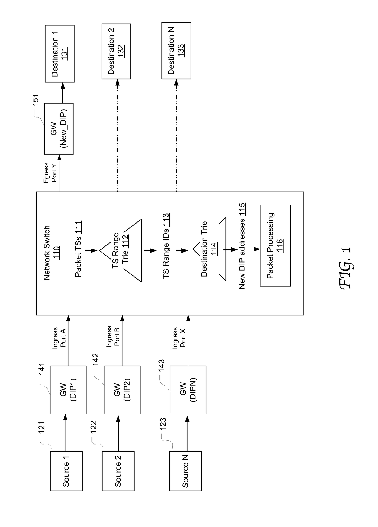
The present disclosure is about a mechanism for efficiently and scalably determining prescribed timestamp ranges for packets received at a network switch. This helps adjust to new protocols and behaviors within the networks. Combining packet timestamps with a trie data structure reduces the memory capacity and bandwidth requirements, and improves search performance even as the timestamp width increases and the lookup table size increases.

Problems solved by technology

As data traffic traverses the network nodes, the data packets are received, buffered, queued, and transmitted, resulting in variable latency and throughput depending on many factors including the link capacity and the traffic load on the network.

Method used


Image

  • Timestamp-based packet switching using a trie data structure
  • Timestamp-based packet switching using a trie data structure
  • Timestamp-based packet switching using a trie data structure

Examples


Embodiment Construction

[0019]Reference will now be made in detail to the preferred embodiments of the present invention, examples of which are illustrated in the accompanying drawings. While the invention will be described in conjunction with the preferred embodiments, it will be understood that they are not intended to limit the invention to these embodiments. On the contrary, the invention is intended to cover alternatives, modifications and equivalents, which may be included within the spirit and scope of the invention as defined by the appended claims. Furthermore, in the following detailed description of embodiments of the present invention, numerous specific details are set forth in order to provide a thorough understanding of the present invention. However, it will be recognized by one of ordinary skill in the art that the present invention may be practiced without these specific details. In other instances, well-known methods, procedures, components, and circuits have not been described in detail ...


PUM


Abstract

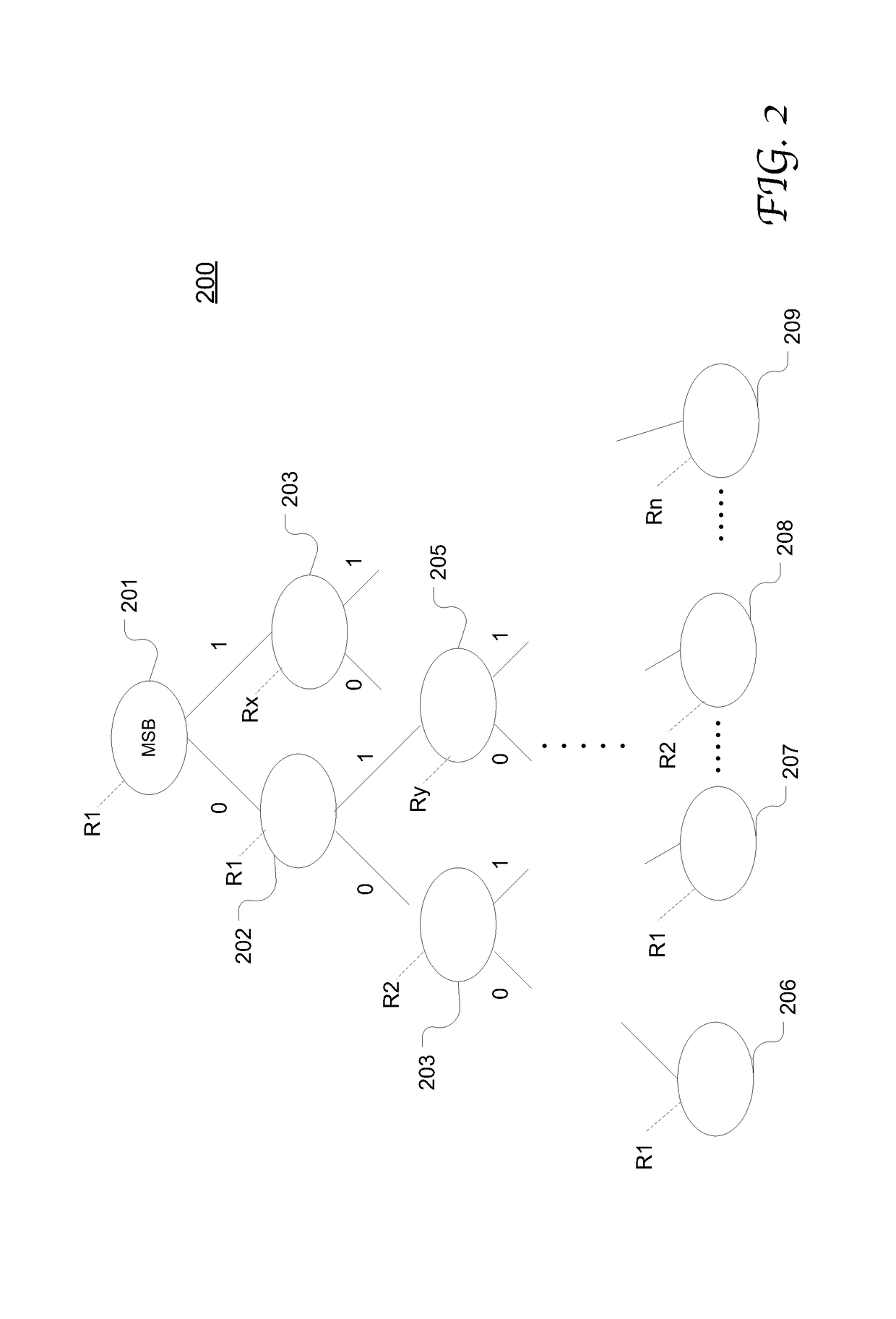
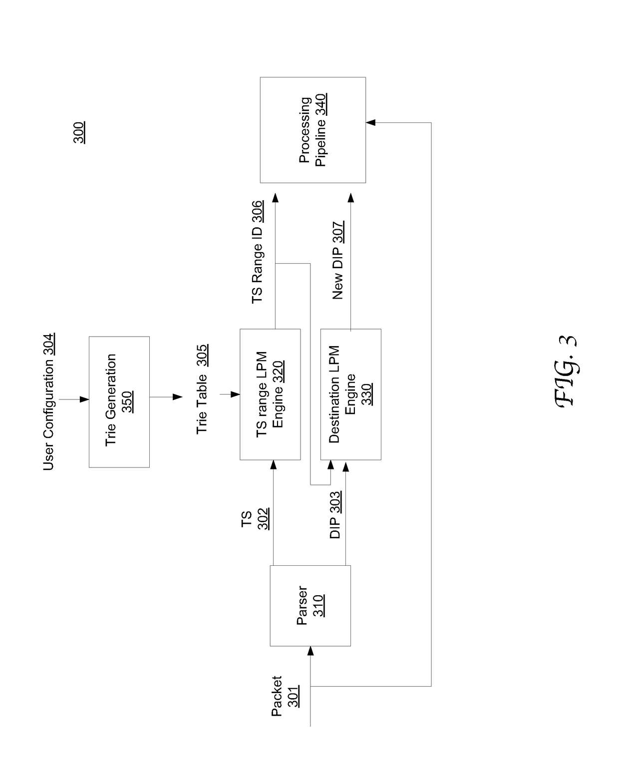
System and method of network packet switching using a table representation of a trie data structure to identify a timestamp (TS) range (or time range) for a received packet based on the packet timestamp (TS). The trie data structure is programmed with a plurality of predetermined time ranges. Each node in the trie data structure corresponds to a TS prefix and is associated with a corresponding predetermined time range. A search engine in the network switch can use the packet TS as a key to traverse the trie data structure and thereby matching the packet TS to a predetermined time range according to a Longest Prefix Match (LPM) process. Provided with the TS ranges of the incoming packets, various applications and logic engines in the network switch can accordingly process the packets, such as determining a new destination IP address and performing channel switch accordingly.

Description

CROSS-REFERENCE TO RELATED APPLICATION[0001]This application claims benefit and priority of the U.S. Provisional Application No. 62 / 516,577, filed on Jun. 7, 2017, entitled “TIMESTAMP-BASED PACKET SWITCHING USING A TRIE DATA STRUCTURE,” the content of which is herein incorporated by reference in entirety for all purposes.TECHNICAL FIELD[0002]Embodiments of the present invention are related to the field of communication network systems, and in particular, to packet switching mechanisms in communication network systems.BACKGROUND[0003]In computer networking, network nodes, such as switches and routers, are typically used to perform packet switching to transmit, receive, process and forward data packets, e.g., between devices or between networks. As data traffic traverses the network nodes, the data packets are received, buffered, queued, and transmitted, resulting in variable latency and throughput depending on many factors including the link capacity and the traffic load on the netwo...

Claims


Application Information

Patent Timeline
IPC IPC(8): H04L12/935H04L29/06H04L12/745H04L12/741H04L29/12H04L49/111H04L45/74H04L45/748
CPCH04L49/3009H04L69/22H04L45/748H04L45/54H04L61/256H04L61/2503
Inventor SHAH, ZUBIN HEMANTKUMARCHEN, SHIH-JEFFSURESH, RAVINDRANLIVAK, LEONID
Owner MARVELL ASIA PTE LTD
Learn More