Refrigeration cycle device

a technology of refrigerating cycle and refrigeration chamber, which is applied in the direction of subcoolers, compression machines with several condensers, lighting and heating apparatus, etc., can solve the problems of reducing the volume of air passing through the interior evaporator, failing to obtain the heat exchange capacity required by the interior evaporator, and freezing of condensed water generated at the surface of the interior evaporator to form frost, etc., to achieve the effect of reducing the amount of fros

Active Publication Date: 2018-12-20
DENSO CORP
View PDF5 Cites 32 Cited by
  • Summary
  • Abstract
  • Description
  • Claims
  • Application Information

AI Technical Summary

Benefits of technology

[0043]Thus, the frost suppression control can be performed to suppress the formation of frost at the cooler core. When the frost suppression control is performed, the heat medium flows to the vehicle-mounted device, so that heat can be absorbed from the vehicle-mounted device. Consequently, even when the amount of heat absorbed from the cooler core is decreased by performing the frost suppression control, such a decrease of the heat absorption amount can be compensated for by the amount of heat absorbed from the vehicle-mounted device, thus ensuring an air blowing temperature to the vehicle interior.
[0044]Therefore, the refrigeration cycle device can achieve both ensuring the air blowing temperature to the vehicle interior and preventing the formation of frost at the cooler core.

Problems solved by technology

However, if the pressure of the refrigerant in the exterior heat exchanger becomes equal to or lower than a certain pressure, condensed water generated at the surface of the interior evaporator is frozen to form frost.
Consequently, the volume of air passing through the interior evaporator is decreased, thus failing to obtain a heat exchange capacity required by the interior evaporator.
However, with such a countermeasure, when the refrigerant flows through the interior evaporator, if the flow rate of a refrigerant flowing through the interior evaporator is reduced, the flow rate of a refrigerant flowing through the exterior heat exchanger is also reduced, so that the heating performance of the interior condenser is more likely to be degraded.

Method used


Image

  • Refrigeration cycle device
  • Refrigeration cycle device
  • Refrigeration cycle device

Examples


first embodiment

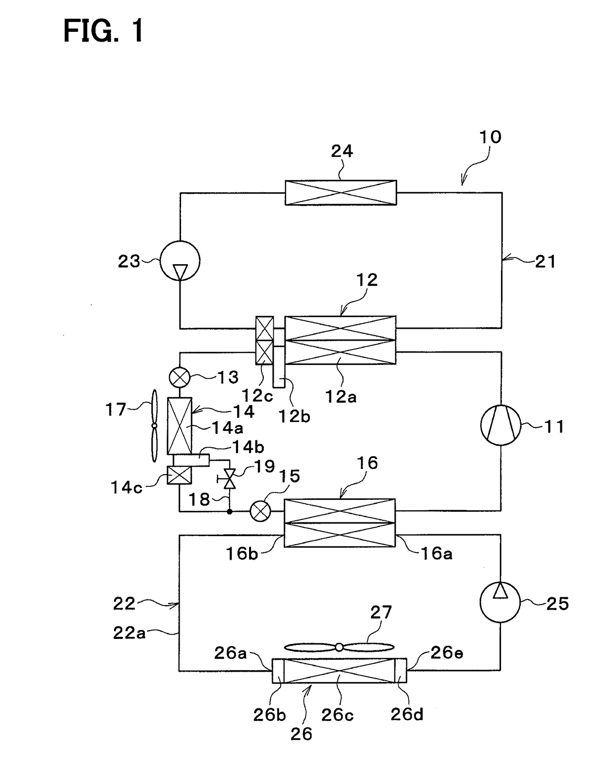
[0068]A refrigeration cycle device 10 shown in FIG. 1 is a vehicle refrigeration cycle device used for adjusting the temperature of an interior space of a vehicle to an appropriate temperature. In the present embodiment, the refrigeration cycle device 10 is applied to a hybrid vehicle that obtains a driving force for traveling from both an engine (in other words, an internal combustion engine) and a traveling electric motor.

[0069]The hybrid vehicle in the present embodiment is configured as a plug-in hybrid vehicle that can charge a battery mounted on the vehicle (in other words, a vehicle-mounted battery) with power supplied from an external power source (in other words, a commercial power source), when the vehicle is stopped. For example, a lithium ion battery can be used as the battery.

[0070]The driving force output from the engine is used not only to cause the vehicle to travel, but also to operate a power generator. The power generated by the power generator and the power suppl...

second embodiment

[0202]As shown in FIGS. 8 and 9, a refrigeration cycle device 10 in the present embodiment includes a heat supply device 40. The heat supply device 40 is a device that supplies heat to the coolant. In the heat supply device 40, the coolant circulates. Examples of the heat supply device 40 include a heat generating device, a ventilation heat recovery heat exchanger, and the like.

[0203]Examples of the heat generating device include an engine, a travelling electric motor, a battery, an inverter, a DC-DC converter, a turbocharger, an intercooler, an EGR cooler, a CVT cooler, and the like.

[0204]The ventilation heat recovery heat exchanger is a heat exchanger that recovers heat exhausted by ventilation. The ventilation heat recovery heat exchanger is the heat exchanger that exchanges heat between the coolant and air discharged from the vehicle interior to the outside of the vehicle cabin for ventilation.

[0205]In a first example shown in FIG. 8, the heat supply device 40 is disposed in the...

third embodiment

[0218]As shown in FIG. 12, a refrigeration cycle device 10 may include an internal heat exchanger 45. The internal heat exchanger 45 has a high-pressure side refrigerant passage 45a and a low-pressure side refrigerant passage 45b.

[0219]The internal heat exchanger 45 is a heat exchanger that exchanges heat between the high-pressure side refrigerant circulating through the high-pressure side refrigerant passage 45a and the low-pressure side refrigerant circulating through the low-pressure side refrigerant passage 45b.

[0220]The high-pressure side refrigerant passage 45a is disposed on the refrigerant-flow downstream side of the exterior heat exchanger 14 and on the refrigerant-flow upstream side of the second expansion valve 15. The low-pressure side refrigerant passage 45b is disposed on the refrigerant-flow downstream side of the low-pressure side heat exchanger 16 and on the refrigerant suction side of the compressor 11.


PUM


Abstract

A refrigeration cycle device includes: a first expansion valve that decompresses a refrigerant flowing out of a high-pressure side heat exchanger; an exterior heat exchanger that exchanges heat between the refrigerant flowing out of the first expansion valve and outside air; a second expansion valve that decompresses the refrigerant flowing out of the exterior heat exchanger; a low-pressure side heat exchanger arranged in series with the exterior heat exchanger; a cooler core that exchanges heat between the heat medium cooled by the low-pressure side heat exchanger and air to be blown into a vehicle interior to cool the air; and a controller configured to switch between a heat absorption mode and a heat dissipation mode by adjusting an amount of decompression in each of the first expansion valve and the second expansion valve.

Description

CROSS REFERENCE TO RELATED APPLICATION[0001]This application is based on Japanese Patent Applications No. 2015-240923 filed on Dec. 10, 2015, and No. 2016-157692 filed on Aug. 10, 2016, the contents of which are incorporated herein by reference in its entirety.FIELD OF THE INVENTION[0002]The present disclosure relates to a refrigeration cycle device that includes a heat exchanger for exchanging heat between a refrigerant and outside air.BACKGROUND ART[0003]Conventionally, for example, Patent Document 1 describes a vehicle refrigeration cycle device that includes a compressor, an interior condenser, a first expansion valve, a second expansion valve, an exterior heat exchanger, an interior evaporator, and an accumulator.[0004]The compressor draws, compresses, and discharges a refrigerant. Refrigerant oil for lubricating the compressor is mixed into the refrigerant, and part of the refrigerant oil circulates within the cycle together with the refrigerant.[0005]The interior condenser is...

Claims


Application Information

Patent Timeline
Patent Type & Authority Applications(United States)
IPC IPC(8): B60H1/32
CPCB60H1/321B60H2001/3255B60H2001/3285B60H2001/3298F25B5/04F25B6/04F25B9/008F25B25/005F25B40/02F25B49/02F25B2309/061F25B2339/047F25B2400/0417F25B2600/2501F25B2600/2513B60H1/00899B60H2001/00928B60H1/32284F25B41/39
Inventor KATO, YOSHIKIHASHIMURA, NOBUYUKIMIURA, KOJIENOMOTO, NORIHIKOSUGIMURA, KENGOSATO, KEIGOTAKEUCHI, MASAYUKIMARASIGAN, ARIEL
Owner DENSO CORP
Why Eureka
Try Eureka