Multiple camera calibration chart

Active Publication Date: 2018-12-20
OMNIVISION TECH INC
View PDF6 Cites 5 Cited by
  • Summary
  • Abstract
  • Description
  • Claims
  • Application Information

AI Technical Summary

Benefits of technology

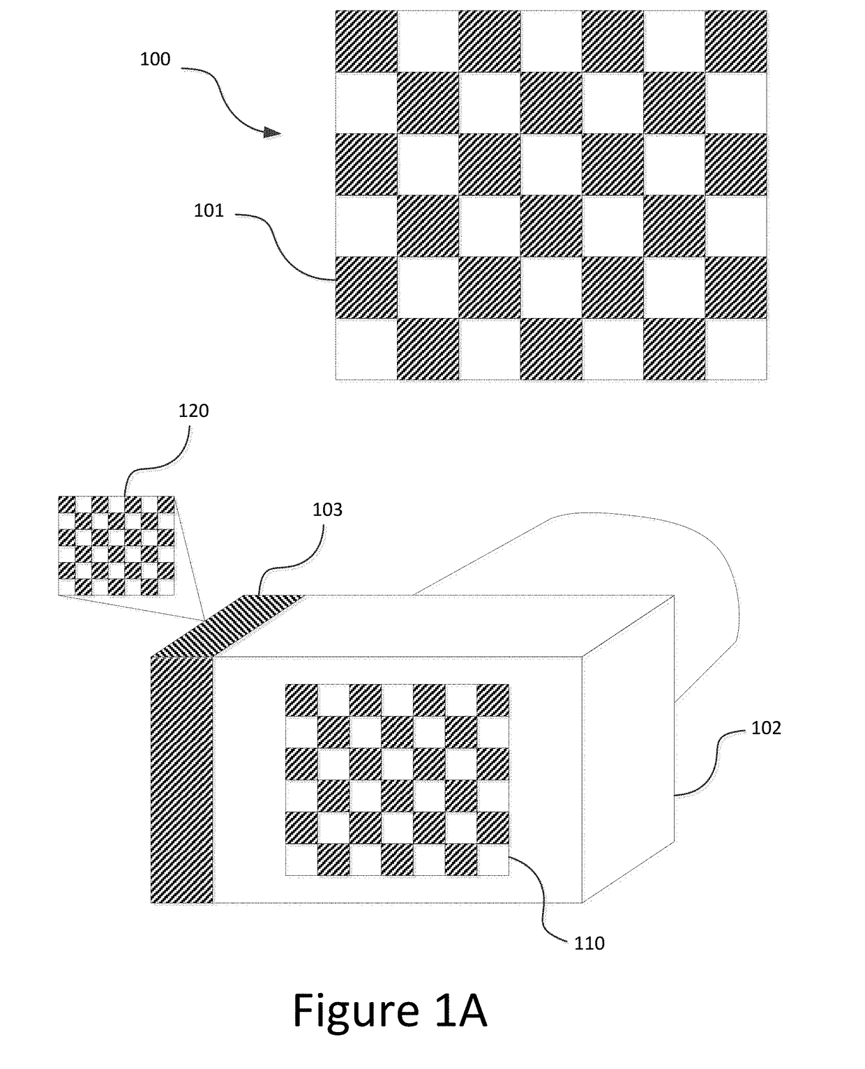
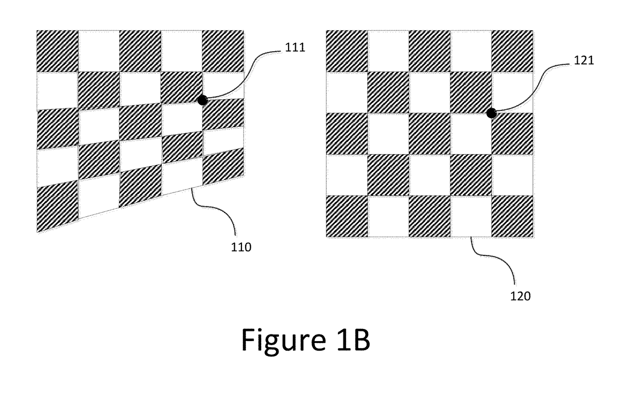
This patent is about calibrating a dual camera module in mobile devices to improve the performance of the camera. The dual camera module includes two cameras with different focal lengths, and can create the impression of an in-depth scene geometry by using triangulation. However, the two cameras will often have distortion and misalignment, which makes it difficult to achieve accurate correspondence matching between the two cameras. To address this, the patent describes a method of calibrating the dual camera module using a dot array calibration chart. The method includes steps to capture images with the dot array calibration chart and deconstruct the images to obtain a pixel level correspondence matching between the two cameras. This allows for improved performance of the dual camera module in creating in-depth scene geometry.

Problems solved by technology

However in reality, the two cameras will often have a certain degree of lens distortion as well as camera position misalignment, due to imperfections of manufacturing and installation.
As a result, the direct correspondence matching is often difficult to achieve, and an estimated depth map becomes unreliable.

Method used


Image

  • Multiple camera calibration chart
  • Multiple camera calibration chart
  • Multiple camera calibration chart

Examples


Embodiment Construction

[0020]In the following description, numerous specific details are set forth to provide a thorough understanding of the examples. One skilled in the relevant art will recognize; however, that the techniques described herein can be practiced without one or more of the specific details, or with other methods, components, materials, etc. In other instances, well-known structures, materials, or operations are not shown or described in detail to avoid obscuring certain aspects.

[0021]Reference throughout this specification to “example” or “embodiment” means that a particular feature, structure, or characteristic described in connection with the example is included in at least one example of the present invention. Thus, the appearances of “example” or “embodiment” in various places throughout this specification are not necessarily all referring to the same example. Furthermore, the particular features, structures, or characteristics may be combined in any suitable manner in one or more exam...


PUM


Abstract

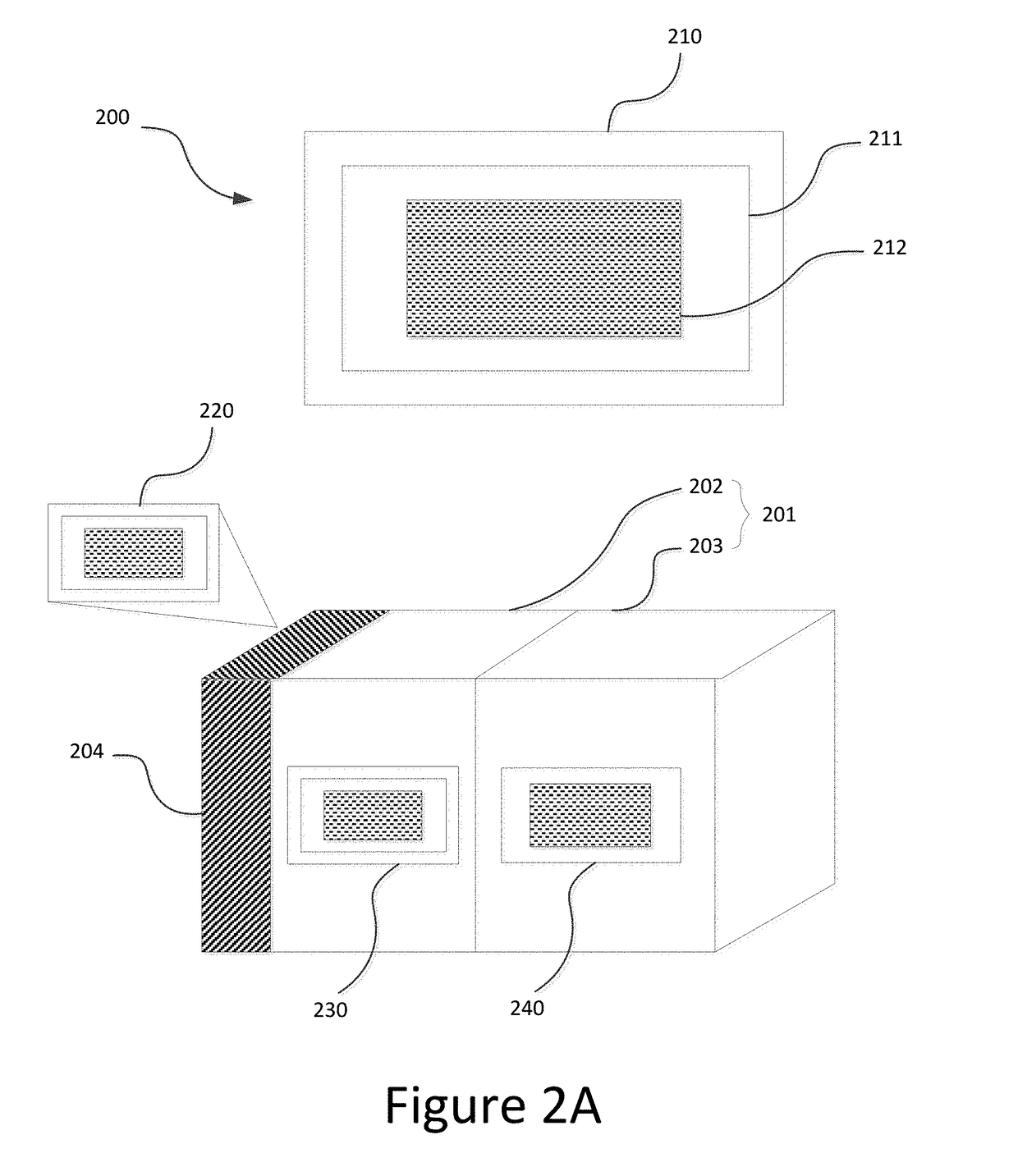
A chart for calibrating a system of multiple cameras, the chart comprising: a background; an array of dots contrasting the background, wherein the array of dots are arranged in rows and columns, wherein the array of dots comprise a first dot array, and a second dot array, wherein the first dot array fully occupies a first region of evenly spaced dots with a first dot density, the second dot array fully occupies a second region of evenly spaced dots with a second dot density, and wherein the second region is enclosed within the first region; a group of first markers in the first region, a group of second markers in the second region, and a third marker at the center of the chart, wherein each second marker is closer to the third marker than each first marker.

Description

TECHNICAL FIELD[0001]This disclosure relates generally to camera calibration systems, and in particular but not exclusively, relates to using a special chart to digitally calibrate a dual camera module. The dual camera module may include two cameras of different focal lengths, such as a wide angle field-of-view (wide-FOV) camera and a telephoto lens camera. The dual camera module may also include two cameras of the same focal length, wherein one camera is a color camera and the other camera is a monochromic camera.BACKGROUND INFORMATION[0002]Mobile devices such as cell phones have a conventional design that includes one rear-facing camera and one front-facing camera. The rear-facing camera is positioned at the backside of the phone, and generally has a higher pixel resolution than the front-facing camera. Recently, manufacturers have been implementing dual camera modules as rear-facing cameras on mobile phones. A dual camera module includes two cameras, for example, a wide field-of-...

Claims


Application Information

Patent Timeline
IPC IPC(8): H04N1/00G06T7/80
CPCG06T7/85H04N1/00045H04N17/002G06T2207/30208
Inventor XU, SHANGAO, XINTINGCHEN, BINTAO, YELIU, GUANSONGCHANG, LU
Owner OMNIVISION TECH INC
Why Eureka
Try Eureka