Work device having a hydraulic drive for civil engineering work

Inactive Publication Date: 2018-12-27
ABI ANLAGENTECHN BAUMASCHEN INDBEBEDARF
View PDF4 Cites 1 Cited by
  • Summary
  • Abstract
  • Description
  • Claims
  • Application Information

AI Technical Summary

Benefits of technology

The invention describes a work device with a hydraulic drive for civil engineering work, such as a drilling device or vibration pile-driving device. The invention allows for temporary heating of the hydraulic fluid without needing additional outside energy. This is achieved through a heat transfer unit that utilizes the waste heat or heat loss of the internal combustion engine. The cooling circuit of the internal combustion engine is also used as a combined material and heat transfer unit, simultaneously cooling the hydraulic fluid and heating it up in a short time. This results in a reduction in fuel consumption and cooling power. Overall, the invention improves the effectiveness of the work device.

Problems solved by technology

Because of the high power loss, the fuel consumption of the internal combustion engine is simultaneously increased.
Furthermore, the hydraulic oil no longer corresponds to the specifications prescribed by the manufacturer of the components of the hydraulic pumps and hydraulic motors, and therefore increased wear must be expected.
Aside from the high amount of energy required here, too, it has proven to be a disadvantage of this solution that hydraulic oil that is situated directly on the mantle surface of a heating rod is heated very much at certain points, and therefore it can be damaged.

Method used


Image

  • Work device having a hydraulic drive for civil engineering work
  • Work device having a hydraulic drive for civil engineering work
  • Work device having a hydraulic drive for civil engineering work

Examples


Embodiment Construction

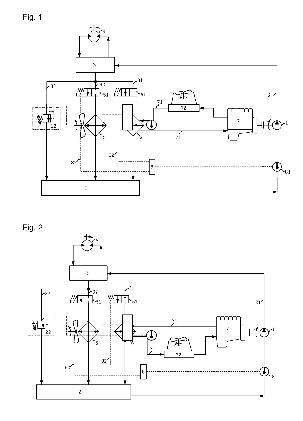
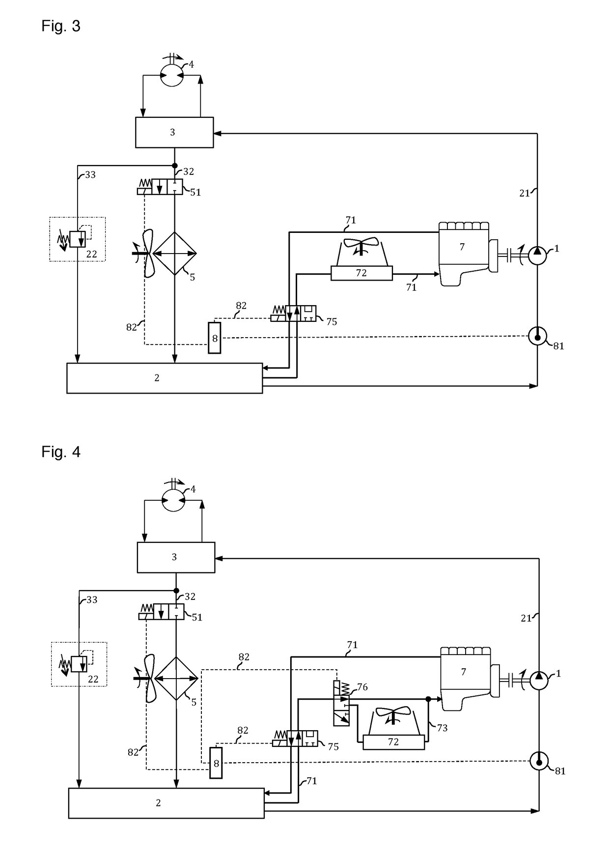
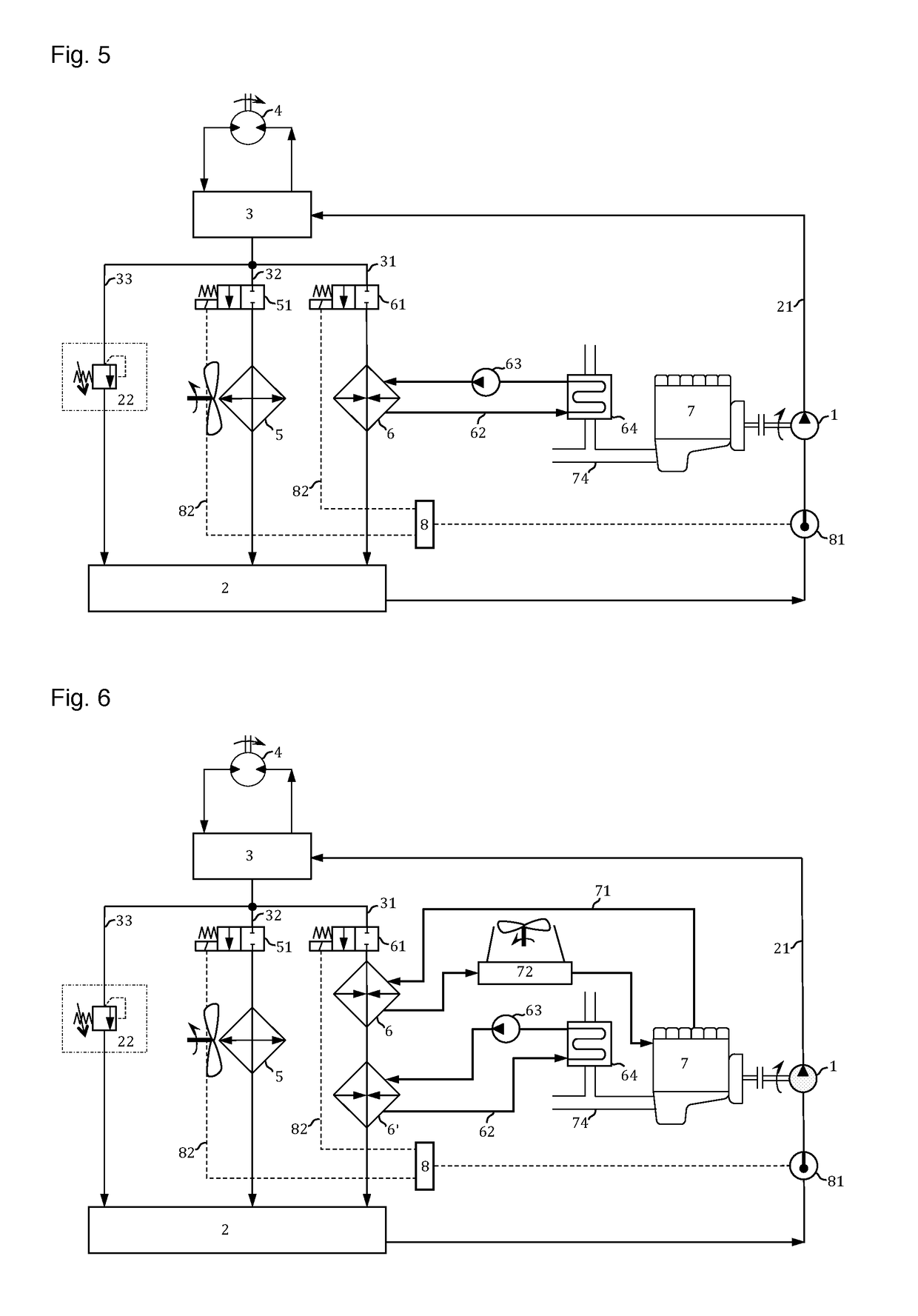
[0034]In FIG. 1, the hydraulic group of a work device having a hydraulic drive for civil engineering work, for example of a drilling device or vibration pile-driving device, is shown schematically. It comprises a hydraulic pump 1, which is disposed in the line 21 between a hydraulic oil tank 2 and a control block 3 and driven by an internal combustion engine 7. The control block 3 is connected with a hydraulic motor 4, the hydraulic oil inflow of which it controls. The control block 3 is connected with the hydraulic oil tank 2 by way of three lines 31, 32, 33 on the return side. The first line 31 is passed by way of a heat exchanger 6 as a coupling line, by way of a 2 / 2-way valve 61. The second line 32 is passed by way of a cooler 5 by way of a further 2 / 2-way valve 51. In the third line 33, a sequence valve 22 is provided as a failure valve, which valve can also be used as a free line to the tank in order to minimize pressure losses.

[0035]Usually, pressure-limiting valves, which ca...


PUM


Abstract

A work device having a hydraulic drive for civil engineering work, in particular a drilling device or vibration pile-driving device, includes a hydraulic motor that is operated by way of a fluid of a hydraulic circuit, which circuit is supplied by way of a hydraulic pump, which pump is driven by an internal combustion engine, wherein at least one heat transfer unit for transfer of thermal energy of a fluid stream of the internal combustion engine to the fluid of the hydraulic circuit is provided. A method temporarily heats the hydraulic fluid of the hydraulic circuit of such a work device.

Description

CROSS REFERENCE TO RELATED APPLICATIONS[0001]Applicant claims priority under 35 U.S.C. § 119 of European Application No. 17177475.5 filed Jun. 22, 2017, the disclosure of which is incorporated by reference.BACKGROUND OF THE INVENTION1. Field of the Invention[0002]The invention relates to a work device having a hydraulic drive for civil engineering work, in particular a drilling device or vibration pile-driving device. The invention furthermore relates to a method for temporary heating of the hydraulic fluid of the hydraulic circuit of a work device having a hydraulic drive for civil engineering work, in particular of a drilling device or vibration pile-driving device.2. Description of the Related Art[0003]In construction, different work devices having a hydraulic drive for civil engineering work are operated in a hydraulic group. The hydraulic group usually consists of a hydraulic pump, which is driven by an internal combustion engine, a work device having a hydraulic drive, in part...

Claims


Application Information

Patent Timeline
IPC IPC(8): F15B21/04F01P3/20F01P7/16F15B1/26F01N3/02F02B29/04F15B21/06
CPCF15B21/042F01P3/20F01P7/16F15B1/26F01N3/0205F02B29/0437F15B21/06E02D7/18E21B7/24F15B2211/20523F15B2211/66Y02T10/12
Inventor HEICHEL, CHRISTIANKLEIBL, ALBRECHT
Owner ABI ANLAGENTECHN BAUMASCHEN INDBEBEDARF
Why Eureka
Try Eureka