
Asynchronous clock-less digital logic path planning apparatus and method

a clockless, logic path technology, applied in pulse techniques, instruments, data processing according to predetermined rules, etc., can solve problems such as increasing the difficulty of problems such as the inability to achieve fast response times, and the inability to meet the requirements of asynchronous processing

Active Publication Date: 2018-12-27
NOKOMIS
View PDF3 Cites 13 Cited by
  • Summary
  • Abstract
  • Description
  • Claims
  • Application Information

AI Technical Summary

Benefits of technology

The patent text discusses the need for a new technology to address the challenge of designing a fast and efficient control system for self-directed vehicles, such as drones and robots, that can operate without substantial computing power or latency. The current solutions require significant computing power and time, which limit their ability to achieve fast response times. The technical effect of this patent is to provide a new or improved technology that can at least partially address this problem and enable the potential capabilities of self-directed vehicles.

Problems solved by technology

Traditional approaches generally can require significant computing power and / or computing time, translating directly to physical watt-hours and kilograms of added weight needed to accomplish this task.
As a result, fast response times may not been achievable with ubiquitous lightweight small land and air vehicles being developed for use worldwide.
Optimizations for minimal time-to-target, fuel usage, safety margins, multiple simultaneous coordinated vehicle path planning, and / or path length minimization add to the difficulty of the problem.
Current technology can require 10's to 100's and even occasionally 1000's of watts when implementing GPU boards with an associated large heavy power source, (and associated cooling capacity), resulting in a system that may not meet the Size, Weight and Power (SWaP) requirements of large drones, much less medium to small units.
This approach, requiring substantial power and volume using even the most up-to-date low-voltage semiconductor dies, with chip process geometries well below 32 nm trace widths, remains a poorly suited solution for single small autonomous mobile robots or drones.

Method used


Image

  • Asynchronous clock-less digital logic path planning apparatus and method
  • Asynchronous clock-less digital logic path planning apparatus and method
  • Asynchronous clock-less digital logic path planning apparatus and method

Examples


Embodiment Construction

[0052]Prior to proceeding to the more detailed description of the present subject matter, it should be noted that, for the sake of clarity and understanding, identical components which have identical functions have been identified with identical reference numerals throughout the several views illustrated in the drawing figures.

[0053]The following detailed description is merely exemplary in nature and is not intended to limit the described examples or the application and uses of the described examples. As used herein, the words “example”, “exemplary” or “illustrative” means “serving as an example, instance, or illustration.” Any implementation described herein as “example”, “exemplary” or “illustrative” is not necessarily to be construed as preferred or advantageous over other implementations. All of the implementations described below are exemplary implementations provided to enable persons skilled in the art to make or use the embodiments of the disclosure and are not intended to l...


PUM


Abstract

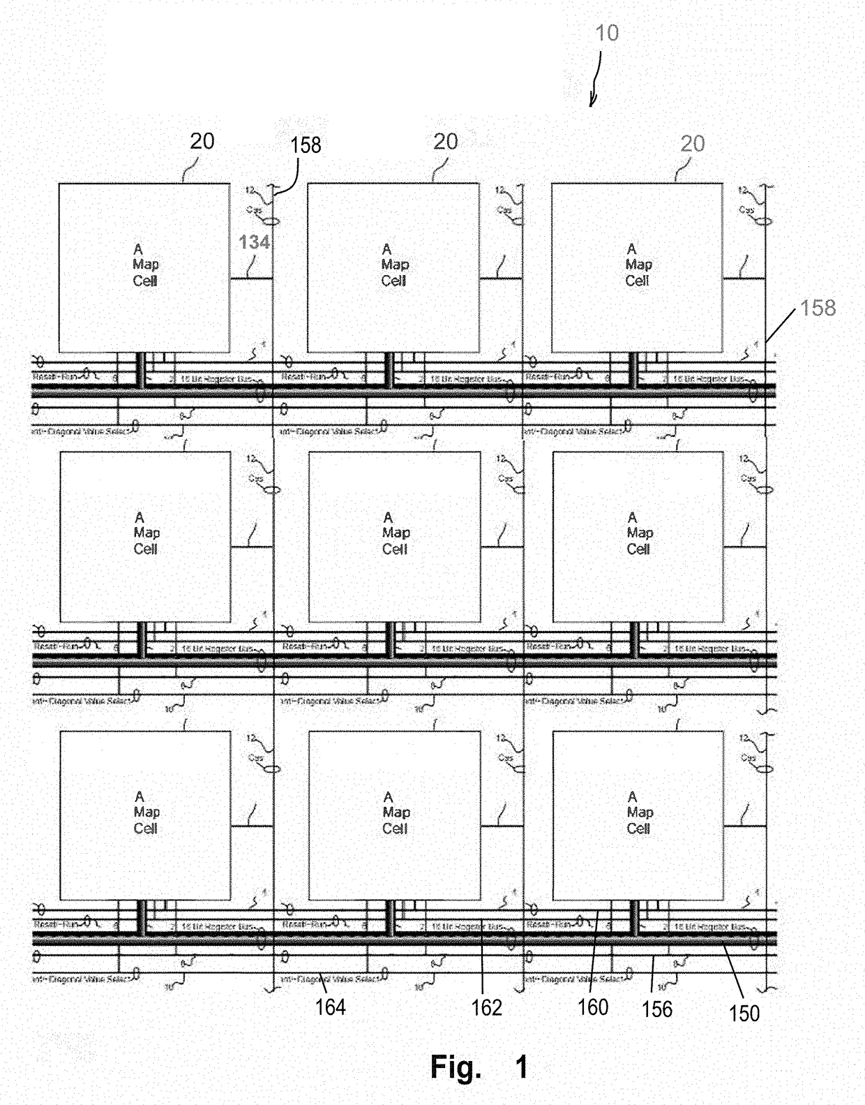
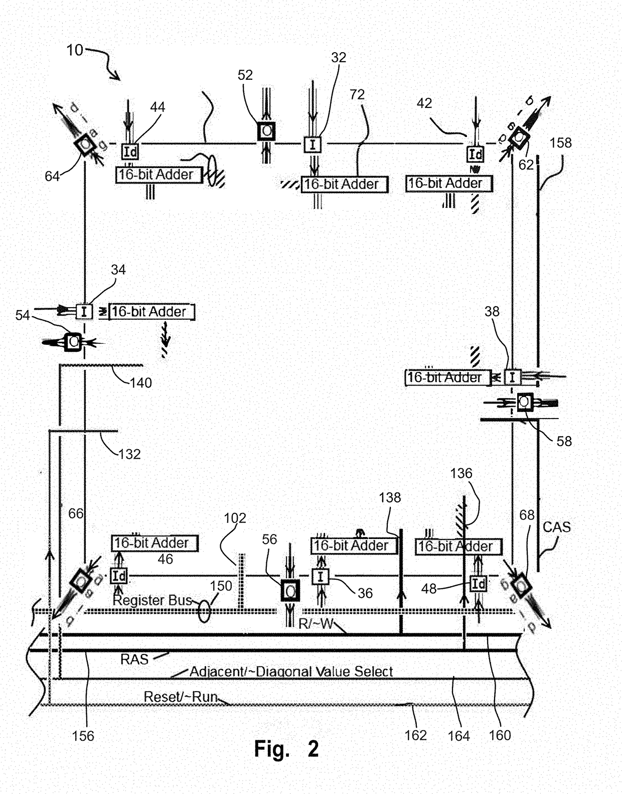
A hybrid of initial time consuming phase of a Single Directional Dijkstra's Algorithm is embodied on an unclocked CMOS logic chip using a parallelized approach with Asynchronous Digital Logic (ADL). The chip includes a a plurality of addressable configurable cells arranged as a multidimensional orthogonal array. The cell array only executes mathematical operations based on a communication between immediately adjacent cells.

Description

CROSS-REFERENCE TO RELATED APPLICATIONS[0001]The present non-provisional application is related to and claims benefit of and priority from provisional U.S. patent application No. 62 / 588,177, titled “Asynchronous Clockless Digital Logic Path Planning Apparatus and Method” and filed on Nov. 17, 2017 by inventor T. Eric Chornenky, the entire contents of which are hereby incorporated by reference thereto. This present non-provisional application is related to and claims benefit of and priority from U.S. Provisional Patent Application Ser. No. 62 / 604,076, titled “Asynchronous Clock-less Digital Logic Path Planning Apparatus and Method” and filed on Jun. 22, 2017 by inventor Eric Chornenky, the entire contents of which are hereby incorporated by reference thereto.STATEMENT REGARDING FEDERALLY SPONSORED RESEARCH AND DEVELOPMENT[0002]N / AREFERENCE TO SEQUENCE LISTING, A TABLE, OR A COMPUTER PROGRAM LISTING COMPACT DISC APPENDIX[0003]N / ABACKGROUND1. Technical Field[0004]The subject matter rel...

Claims


Application Information

Patent Timeline
Patent Type & Authority Applications(United States)
IPC IPC(8): G05D1/00G06F3/06B60R16/023G05D1/02
CPCG05D1/0088G06F3/0604G06F3/061G06F3/0659G06F3/0688B60R16/0231G05D1/0278G11C5/025G11C7/106G11C7/1087G11C7/109G11C7/22H03K3/037G06F15/00G11C7/10G06F7/76H03K19/177
Inventor CHORNENKY, T. ERIC
Owner NOKOMIS
Learn More