
Backlight driving circuit and liquid crystal display

a technology of backlight driving circuit and liquid crystal display, which is applied in the field of display, can solve the problems of high inability to meet safety standards, and complex backlight power supply circuit as driving large-scale products, etc., and achieve the effect of reducing the temperature of drive switch transistor

Active Publication Date: 2018-12-27
TCL CHINA STAR OPTOELECTRONICS TECH CO LTD
View PDF0 Cites 1 Cited by
  • Summary
  • Abstract
  • Description
  • Claims
  • Application Information

AI Technical Summary

Benefits of technology

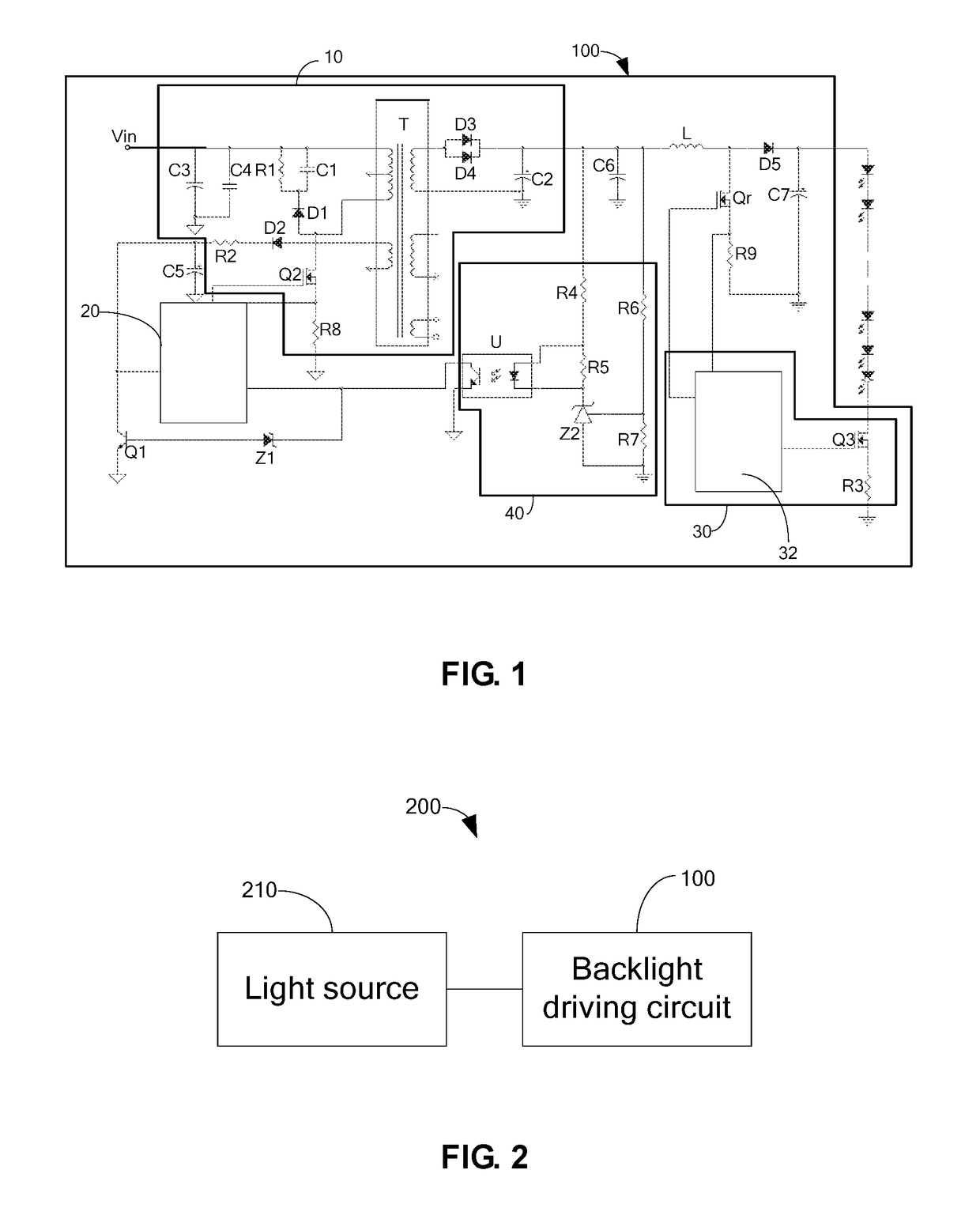
The present invention provides a backlight driving circuit that reduces the temperature of the drive switch transistor to meet safety standards. The circuit includes a voltage conversion circuit, a PWM controller, a zener diode, a first electrical switch, an optocoupler, a boost switch, and a light source drive assembly. The voltage conversion circuit converts the input voltage, and the PWM controller controls the output of the voltage conversion circuit. The light source drive assembly controls the on and off of the boost switch based on the light source condition. The zener diode is used as a voltage reduction device, and it is connected to the optocoupler, the PWM controller, and the first electrical switch. The boost switch is short-circuited when the current output of the voltage conversion circuit exceeds a certain level, and the zener diode is turned on to stop the PWM controller from turning off the boost switch. This results in a reduction of the surface temperature of the boost switch, and it also protects the over-current.

Problems solved by technology

The backlight power supply circuit as driving the large-scale products, such as televisions, is more complex.
The PWM integrated chip is restarted for a period of time to result in a high temperature of the drive switch transistor and thus the safety standards are not met.

Method used


Image

  • Backlight driving circuit and liquid crystal display

Examples


Embodiment Construction

[0022]Embodiments of the present invention are described in detail with the technical matters, structural features, achieved objects, and effects with reference to the accompanying drawings as follows. It is clear that the described embodiments are part of embodiments of the present invention, but not all embodiments. Based on the embodiments of the present invention, all other embodiments to those of ordinary skill in the premise of no creative efforts obtained, should be considered within the scope of protection of the present invention.

[0023]Besides, the following descriptions for the respective embodiments are specific embodiments capable of being implemented for illustrations of the present invention with referring to appended figures. For example, the terms of up, down, front, rear, left, right, interior, exterior, side, etcetera are merely directions of referring to appended figures. Therefore, the wordings of directions are employed for explaining and understanding the prese...


PUM

PropertyMeasurementUnit
voltageaaaaaaaaaa
breakdown voltageaaaaaaaaaa
temperatureaaaaaaaaaa

Abstract

Provided is a backlight driving circuit, comprising voltage conversion circuit, PMW controller, zener diode, first electrical switch, optocoupler unit, boost switch and light source drive assembly. The PMW controller controls an output of the voltage conversion circuit. The light source drive assembly is connected to the boost switch and a light source to control on and off of the boost switch. A cathode of the zener diode is connected to the optocoupler unit, and an anode of the zener diode is connected to a control end of the first electric switch, and a first end of the first electrical switch is connected to the PWM controller, and a second end of the first electrical switch is grounded, and as the boost switch is short, a current outputted by the voltage conversion circuit increases, and the optocoupler unit breaks the zener diode down.

Description

CROSS REFERENCE[0001]This application claims the priority of Chinese Patent Application No. 2017100899938, entitled “Backlight driving circuit and liquid crystal display”, filed on Feb. 20, 2017, the disclosure of which is incorporated herein by reference in its entirety.FIELD OF THE INVENTION[0002]The present invention relates to a display technical field, and more particularly to a voltage output control circuit and a liquid crystal display.BACKGROUND OF THE INVENTION[0003]In the present panel design, the proportion of the large-scale products gradually increased. The backlight power supply circuit as driving the large-scale products, such as televisions, is more complex. In the present television backlight driving circuit, due to the boost of the light emitting diode, the drive switch transistor will occur short circuit phenomenon. In the backlight driving circuit, the transformer primary over-power protection method is usually utilized. The PWM integrated chip is restarted for a...

Claims


Application Information

Patent Timeline
Patent Type & Authority Applications(United States)
IPC IPC(8): G09G3/34G02F1/1335G02F1/133G09G3/36
CPCG09G3/3406G02F1/133602G02F1/13306G09G3/3648G09G2320/064G02F2001/133612G02F1/133612
Inventor LI, WENDONG
Owner TCL CHINA STAR OPTOELECTRONICS TECH CO LTD
Learn More