
Resistance spot welding method and welded member production method

a production method and spot welding technology, applied in welding equipment, metal working equipment, manufacturing tools, etc., can solve the problems of high labor intensity, limited use of steel sheets that satisfy the required properties, and high labor intensity, and achieve significant compressive plastic deformation, high tensile stress, and increased possibility of cracking

Active Publication Date: 2019-01-03
JFE STEEL CORP
View PDF3 Cites 5 Cited by
  • Summary
  • Abstract
  • Description
  • Claims
  • Application Information

AI Technical Summary

Benefits of technology

The present invention proposes a resistance spot welding method and a welded member production method that can prevent cracking in the weld caused by axis misalignment between electrodes regardless of the steel grade. By reducing the temperature of the weld and inhibiting the low melting point metal from penetrating the grain boundaries of the steel sheet, the occurrence of cracking can be reduced.

Problems solved by technology

However, Patent Literature 1 poses a problem in that, for example, since limitations need to be imposed on the contents of the alloying elements in the steel sheets, usable steel sheets that satisfy the required properties are limited.
Thus, the application is extremely limited particularly because, currently, high-alloy steel sheets are increasingly being produced for increased strength.
Patent Literature 3 poses a problem in that optimization of the welding conditions requires many man-hours and that the method cannot be applied to steel sheets and sheet combinations for which providing an appropriate current range is difficult.
In addition, neither Patent Literature 2 nor 3 considers the influence of axis misalignment between the electrodes, and therefore their measures are insufficient in some cases in view of the implementation steps in the assembly of automobiles.

Method used


Image

  • Resistance spot welding method and welded member production method
  • Resistance spot welding method and welded member production method
  • Resistance spot welding method and welded member production method

Examples


examples

[0089]The following describes examples according to the present invention. Resistance spot welding was performed on sheet combinations, each of which included two or three overlapping sheets, to produce joints (welded members). The sheet combinations are shown in Table 1, and the conditions used are shown in Table 2 (Table 2-1 to Table 2-3). In the specimens of this example, the melting point of the base material ranges from 1400 to 1570° C., the melting point of the galvanized coating (GI) ranges from 400 to 500° C., and the melting point of the galvannealed coating (GA) ranges from 600 to 950° C. The tensile strengths shown in Table 1 are tensile strengths determined in the following manner. From each of the steel sheets, a JIS No. 5 tensile test specimen was taken in a direction parallel to the rolling direction, and a tensile test was conducted according to JIS Z 2241: 2011. In Table 2, the electrode forces F in the step of retaining the electrode force after completion of curre...


PUM

PropertyMeasurementUnit
tensile strengthaaaaaaaaaa
distanceaaaaaaaaaa
thicknessesaaaaaaaaaa

Abstract

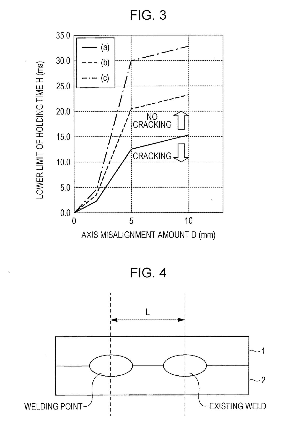
Provided is a resistance spot welding method that inhibits, in accordance with the degree of axis misalignment between electrodes, the occurrence of cracking in a weld regardless of the steel grade. In resistance spot welding methods according to the present invention, H (ms) is an electrode force retaining time after completion of current passage, D (mm) is an amount of axis misalignment between the electrodes, t (mm) is a total sum of sheet thicknesses of a plurality of overlapping steel sheets, T (MPa) is a tensile strength of a steel sheet having a highest tensile strength among the plurality of steel sheets, F (N) is an electrode force, and d (mm) is a tip diameter of one electrode of the pair of electrodes that has a smaller tip diameter. The electrode force retaining time H is specified to be a predetermined value or greater.

Description

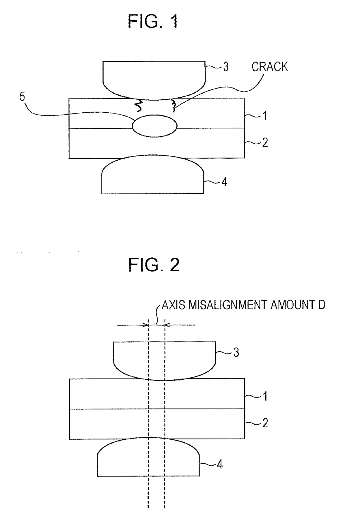
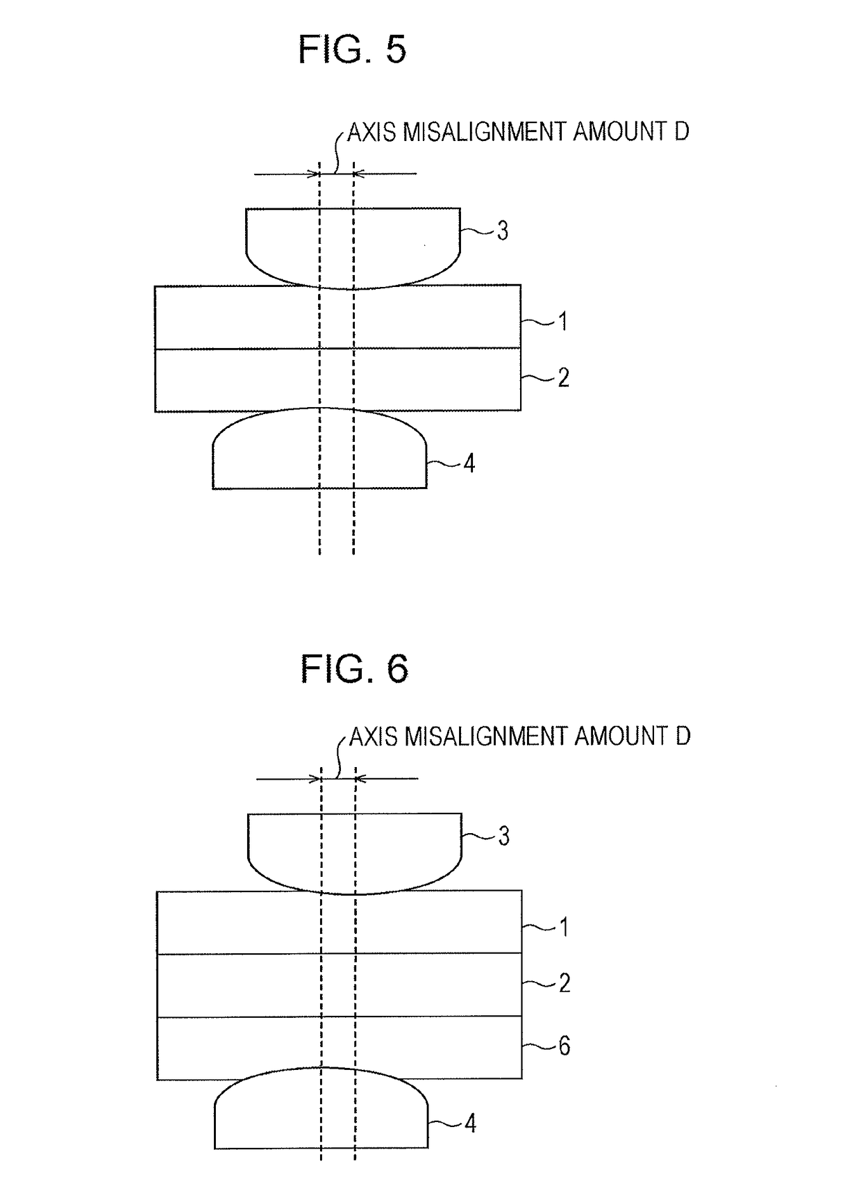
CROSS REFERENCE TO RELATED APPLICATIONS[0001]This is the U.S. National Phase application of PCT / JP2016 / 087014, filed Dec. 13, 2016, which claims priority to Japanese Patent Application No. 2015-244823, filed December 16, 2015, the disclosures of these applications being incorporated herein by reference in their entireties for all purposes.TECHNICAL FIELD OF THE INVENTION[0002]The present invention relates to a resistance spot welding method and a′ welded member production method.BACKGROUND OF THE INVENTION[0003]A resistance spot welding method is a type of lap resistance welding method and is typically used to join overlapping steel sheets together. The welding method is performed as follows. As illustrated in FIG. 1, two or more overlapping steel sheets 1 and 2 are squeezed between a pair of electrodes 3 and 4 from above and below. While a force is being applied to the steel sheets by the upper and lower electrodes, a high welding current is passed therethrough for a short time to ...

Claims


Application Information

Patent Timeline
Patent Type & Authority Applications(United States)
IPC IPC(8): B23K11/11B23K11/16
CPCB23K11/115B23K11/166B23K11/16B23K11/163B23K2101/34
Inventor SAWANISHI, CHIKAUMITANIGUCHI, KOICHITAKASHIMA, KATSUTOSHIMATSUDA, HIROSHIIKEDA, RINSEI
Owner JFE STEEL CORP
Learn More