
Apparatus and method for film formation by physical sputtering

a technology of physical sputtering and apparatus, which is applied in the direction of vacuum evaporation coating, electric discharge tube, coating, etc., can solve the problems of unremitting consumption of target material, influence of backboard and product, etc., to achieve effective avoid backboard damage and abnormality of product resulting, improve product quality, and simple structure

Active Publication Date: 2019-01-03
WUHAN CHINA STAR OPTOELECTRONICS TECH CO LTD
View PDF5 Cites 0 Cited by
  • Summary
  • Abstract
  • Description
  • Claims
  • Application Information

AI Technical Summary

Benefits of technology

This patent describes an apparatus and method for film formation by physical sputtering that have several technical effects. The apparatus has a simple structure and can monitor the consumption of the target material in real time, which helps to improve the quality of the product. This also avoids waste of the material. The method is simple to operate and can ensure the product quality by avoiding breakdown of the target material during film formation of the substrate. The use efficiency of the target material can also be improved, which helps to avoid waste of the material. Overall, this patent demonstrates how to improve the efficiency and accuracy of film formation by physical sputtering.

Problems solved by technology

With the passing of time, the target material is consumed unremittingly.
Currently, the completion of the consumption of the target material on the machine cannot be found out in time, which may easily cause the situation of the breakdown of the target material, and thus influence the backboard and the product.

Method used


Image

  • Apparatus and method for film formation by physical sputtering
  • Apparatus and method for film formation by physical sputtering
  • Apparatus and method for film formation by physical sputtering

Examples


Embodiment Construction

[0035]In combination with the drawings and the description of the specific embodiments of the present disclosure, the details of the present disclosure can be clearly understood. However, the specific embodiments of the present disclosure described herein are merely for illustrating the purpose of the present disclosure rather than being regarded as the limitations to the present disclosure in any means. Under the guidance of the present disclosure, a skilled person can conceive any possible variation based on the present disclosure. This should be regarded as within the scope of the present disclosure. In the following part, the present disclosure will be further illustrated in combination with the drawings.

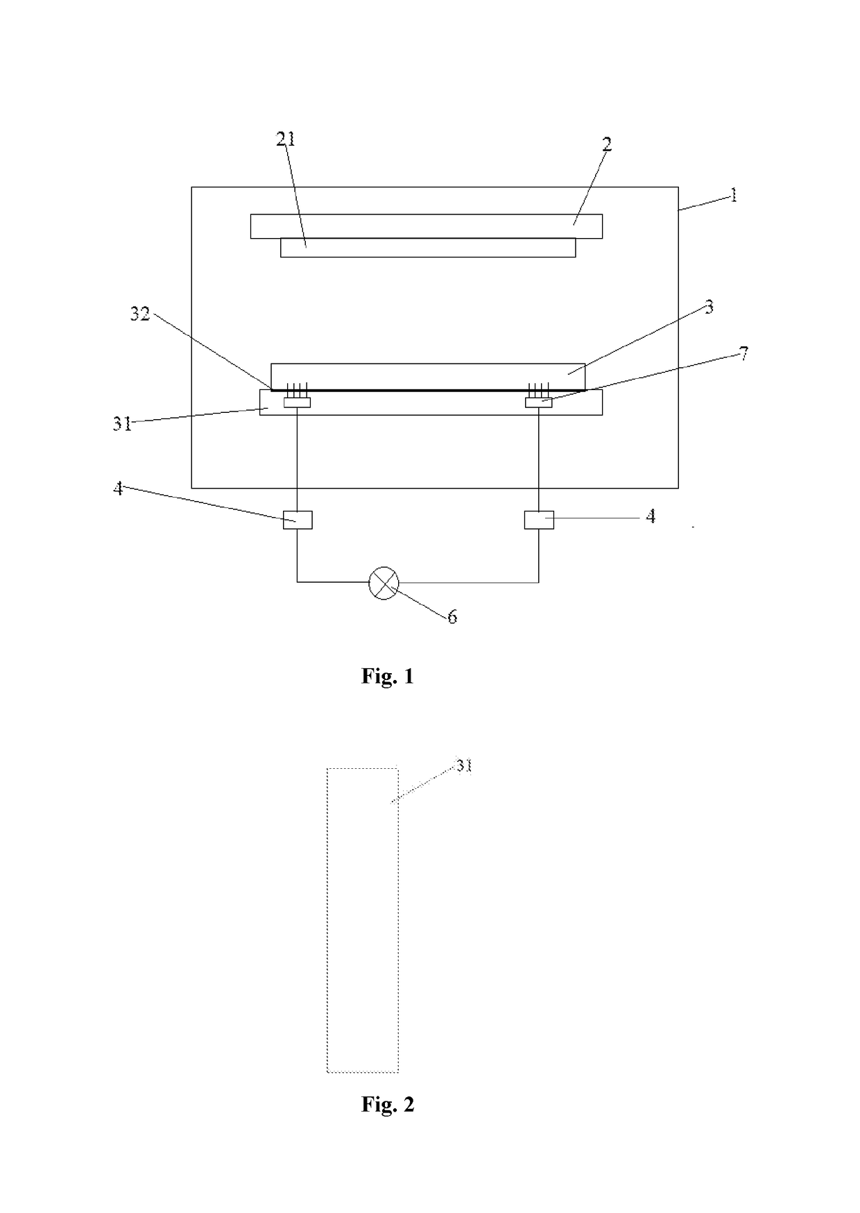
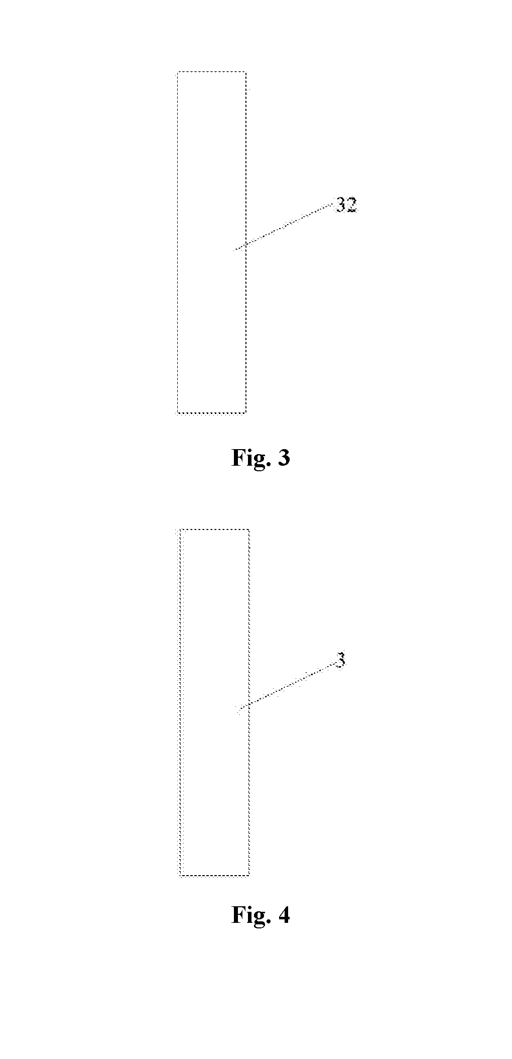
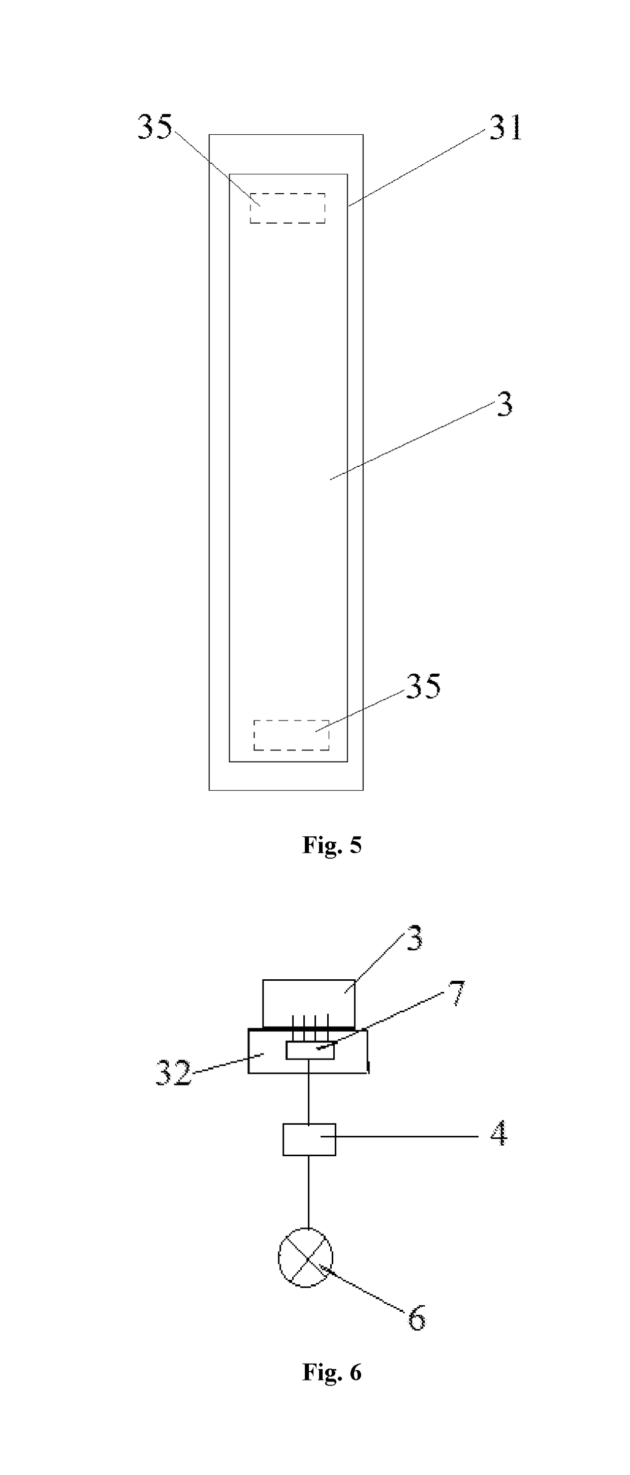
[0036]FIG. 1 to FIG. 6 respectively show a structural diagram of an apparatus for film formation by physical sputtering, a structural diagram of a target material, a structural diagram of a target material backboard, a structural diagram of a bonding layer, a structural diagram ...


PUM

PropertyMeasurementUnit
Electrical resistanceaaaaaaaaaa

Abstract

Disclosed is an apparatus for film formation by physical sputtering, which includes a vacuum chamber; a substrate platform arranged inside of the chamber, and provided thereon with a substrate to be formed with a film; a target material arranged inside of the chamber, and arranged opposite to the substrate; at least one square resistance meter, which is connected to the target material to real-timely measure an actual resistance value of the target material; an excitation source, which is used to bombard the target material for sputtering atoms of the target material; and a control system, which is connected to the square resistance meter. The apparatus for film formation by physical sputtering has a simple structure, can monitor the consumption of the target material in real time, effectively avoid damage of a backboard and abnormality of a product resulting from breakdown of the target material, and improve the quality of the product. Meantime, the use efficiency of the target material can be improved and thus the waste of the material, which would otherwise be caused by incomplete use of the target material, can be avoided.

Description

CROSS-REFERENCE TO RELATED APPLICATIONS[0001]This application claims the priority of Chinese patent application CN 201710298657.4, entitled “Apparatus and method for film formation by physical sputtering” and filed on Apr. 27, 2017, the entirety of which is incorporated herein by reference.FIELD OF THE INVENTION[0002]The present disclosure relates to the technical field of film formation on a substrate, and in particular, to an apparatus and a method for film formation by physical sputtering.BACKGROUND OF THE INVENTION[0003]In a procedure of manufacturing a thin film transistor (TFT) substrate, it is required to deposit Al, Mo, Ti, Cu and other metal films, and ITO, IGZO and other non metal films on a glass substrate. The manufacturing procedure is usually achieved by using a physical vapor deposition (PVD) machine. The working principle of PVD is to use Ar ions in a plasma to bombard a target material for sputtering the atoms of the target material and transferring the atoms to a s...

Claims


Application Information

Patent Timeline
IPC IPC(8): C23C14/34C23C14/56C23C14/52
CPCC23C14/3492C23C14/56C23C14/52C23C14/34C23C14/54C23C14/3407H01J37/34H01J37/3476
Inventor LIU, SIYANG
Owner WUHAN CHINA STAR OPTOELECTRONICS TECH CO LTD
Learn More