
Technologies of controlling additive manufacturing systems

a technology of additive manufacturing and control technology, applied in the field of manufacturing system control, can solve the problems of uncontrollable variations in the set of additive manufacturing parameters, unfavorable workpiece characteristics, and difficult processing in real-time, and achieve the effect of reducing data conflicts and reducing active feedback

Inactive Publication Date: 2019-01-03
NORSK TITANIUM
View PDF0 Cites 7 Cited by
  • Summary
  • Abstract
  • Description
  • Claims
  • Application Information

AI Technical Summary

Benefits of technology

The present disclosure provides various technical solutions to problems in manufacturing using advanced technology. The solutions involve a program that can access subroutines and libraries to control manufacturing parameters and manage configurations, resulting in improved consistency and repeatability across multiple machines. The program also reduces data conflicts by avoiding or minimizing such conflicts based on input workpiece identifiers.

Problems solved by technology

However, a technical problem exists when the active feedback from the set of sensors contains a large set of data.
In particular, the large set of data is not only difficult to process in real-time, especially if data conflicts exist, but also can result in some uncontrolled variations in the set of additive manufacturing parameters during manufacturing, such as a traverse speed, a melt pool energy input, a thermal condition, or others.
Such uncontrolled variations can result in some undesired workpiece characteristics, such as excessive material voids, low material strength, unwanted material properties, disproportionate material porosity, or others.
Resultantly, the uncontrolled variations can have an adverse impact on an additive manufacturing workflow and on an ability to produce workpieces that have consistently repeatable material properties, which is especially important when seeking approval of safety regulators, such as in aerospace applications, automotive applications, medical applications, or others.
Furthermore, when the additive manufacturing system includes a metal deposition system, then the technical problem becomes more complex as most conventional metal deposition processes are not repeatable over time on a same machine basis and across multiple machines.

Method used


Image

  • Technologies of controlling additive manufacturing systems
  • Technologies of controlling additive manufacturing systems
  • Technologies of controlling additive manufacturing systems

Examples


Embodiment Construction

[0043]This disclosure is now described more fully with reference to the set of accompanying drawings, in which some embodiments of this disclosure are shown. This disclosure can, however, be embodied in many different forms and should not be construed as necessarily being limited to the embodiments disclosed herein. Rather, these embodiments are provided so that this disclosure is thorough and complete, and fully conveys various concepts of this disclosure to skilled artisans. Reference will now be made in detail to an embodiment of this disclosure, an example of which is illustrated in the set of appended drawings.

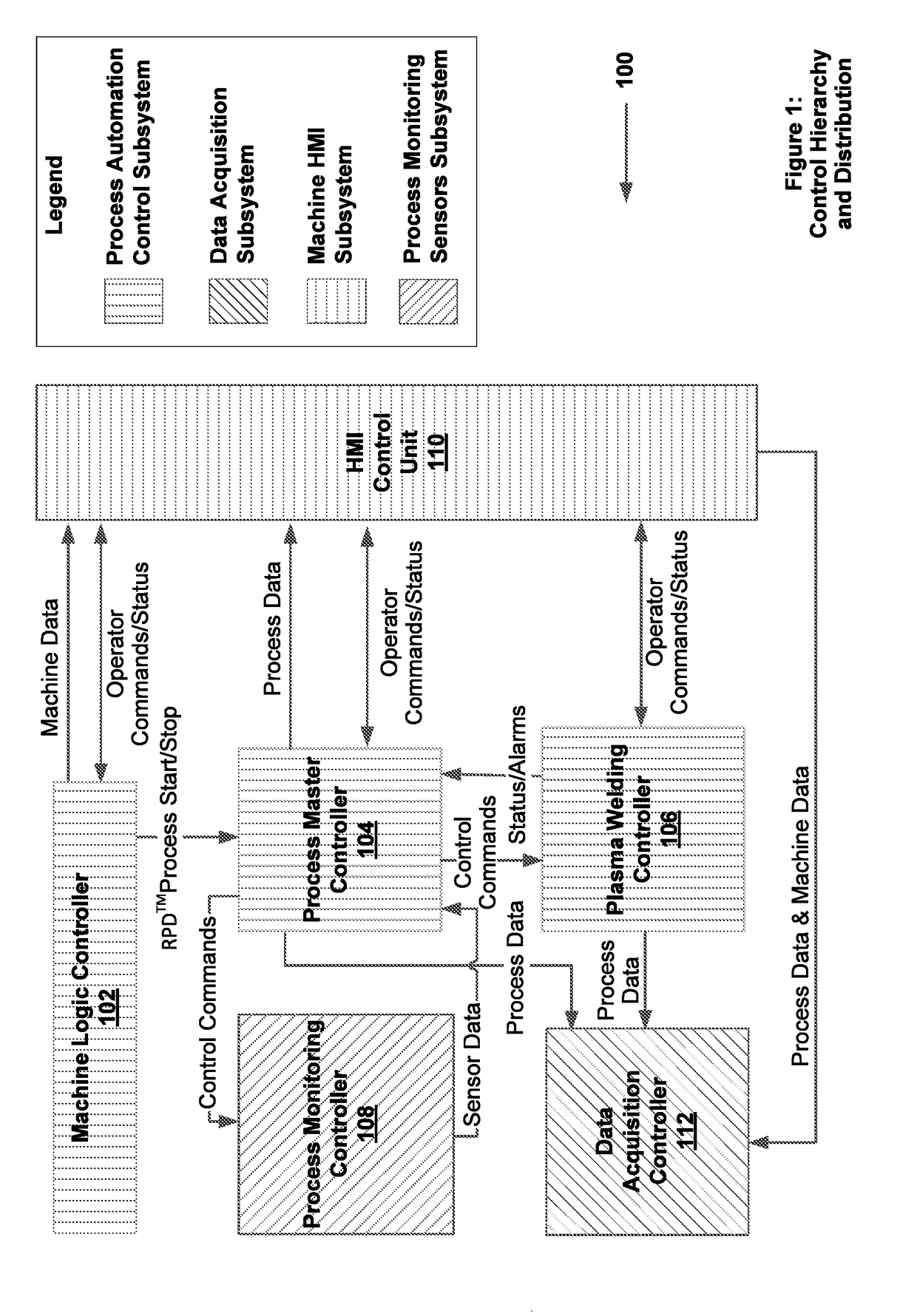
[0044]FIG. 1 is a block diagram of an embodiment of a control hierarchy and distribution schema of a manufacturing system according to this disclosure. In particular, a control hierarchy and distribution schema 100 of an additive manufacturing system is disclosed. For example, the additive manufacturing system can include a metal deposition system, a 3-D printing system, ...


PUM

PropertyMeasurementUnit
timeaaaaaaaaaa
distanceaaaaaaaaaa
distanceaaaaaaaaaa

Abstract

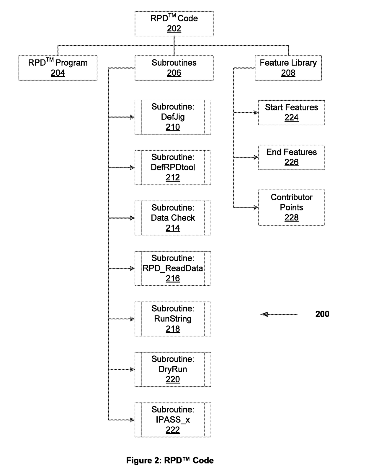
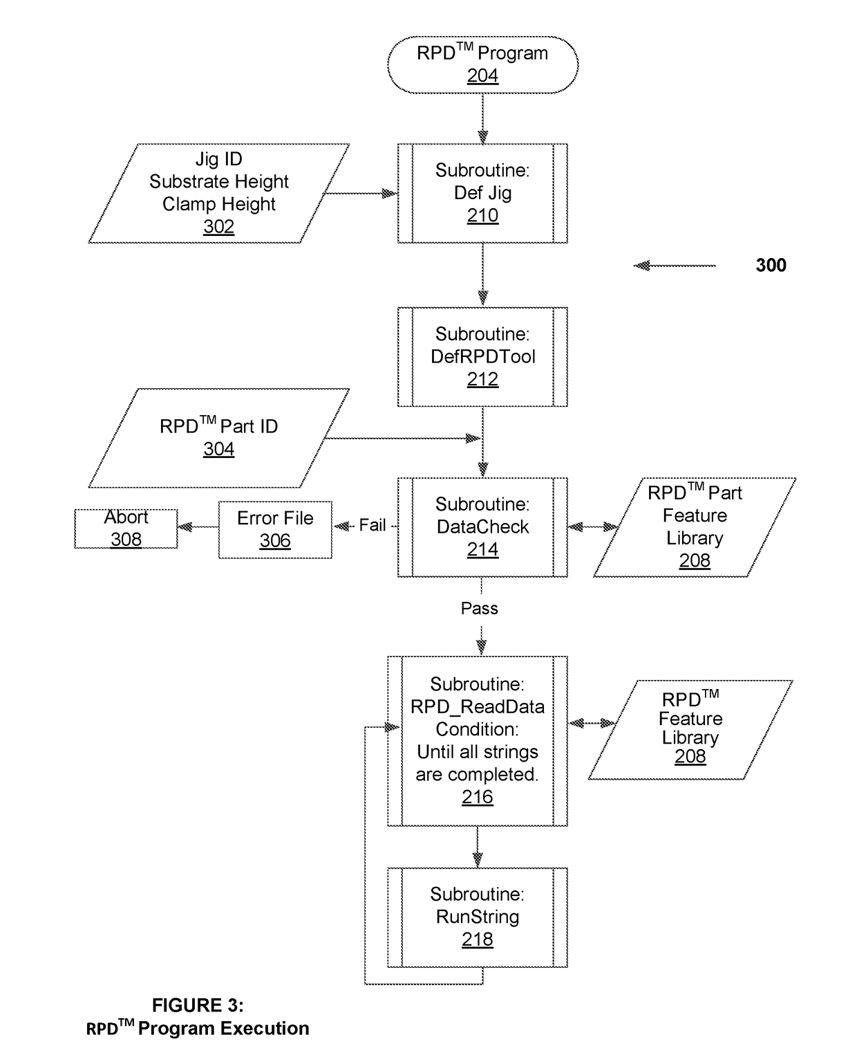
A system / method for executing a program accessing a plurality of subroutines / libraries; invoking a first subroutine providing the program with axis data having offset values in accordance with a workpiece coordinate system; invoking a second subroutine providing the program with geometric data about a geometric of an additive manufacturing tool and setting a tool offset point of the tool at a distance above a substrate surface; receiving a workpiece identifier from an HMI; invoking a third subroutine providing the program with rapid plasma deposition part programming instructions and rapid plasma deposition features from one of the libraries based on the workpiece identifier; invoking a fourth subroutine verifying the instructions and the rapid plasma deposition features; and invoking a fifth subroutine enabling the program to request an additive manufacturing system to deposit a layer on the substrate surface by the additive manufacturing tool via the additive manufacturing process.

Description

[0001]This application claims the priority benefit of U.S. Provisional Application No. 62 / 527,459 filed on Jun. 30, 2017, and which is hereby incorporated by reference in its entirety for all purposes as if fully set forth herein.BACKGROUNDTechnical Field[0002]Generally, this disclosure relates to manufacturing systems. More particularly, this disclosure relates to process architectures for control of manufacturing systems.Discussion of Related Art[0003]An additive manufacturing system, such as an additive metal deposition system or others, can rely on active feedback from a set of sensors in order to control, in real-time, a set of additive manufacturing parameters, such as a fed-stock rate, a stand-off distance, a plasma gas flow, a main current, a plasma transferred arc (PTA) current, a preheat current, or others. For example, an additive manufacturing system with an Interlayer Real-time Imaging and Sensing System (IRISS) technology includes a real-time adaptive control system th...

Claims


Application Information

Patent Timeline
Patent Type & Authority Applications(United States)
IPC IPC(8): G05B19/4099G05B19/409B29C64/393B29C64/371
CPCG05B19/4099G05B19/409B29C64/393B29C64/371G05B2219/23067G05B2219/13005G05B2219/36133G05B2219/49007B33Y50/02B33Y10/00G05B2219/49019G05B2219/49029
Inventor H KENRUD, KRISTERVIGDAL, BREDE
Owner NORSK TITANIUM
Learn More