Artroscopic devices and methods

a technology of cutting and removing devices and arthroscopic tissue, which is applied in the field of arthroscopic tissue cutting and removal devices, can solve the problems of limited force and drawbacks of limited force transmitted to the jaw structure, and achieve the effects of increasing force, maximizing mechanical advantage obtained in driving the jaw structure, and increasing closing for

Active Publication Date: 2019-01-10
RELIGN CORP
View PDF0 Cites 18 Cited by
  • Summary
  • Abstract
  • Description
  • Claims
  • Application Information

AI Technical Summary

Benefits of technology

[0010]In particular, the pitch and spacing of the helical threads mating between the first and second drive elements will be selected to axially translate the second drive in a direction opposite to the direction in which the first drive element is being driven. By having the first and second drive elements move in opposite directions relative to the hub, the number of rotations of the drive shaft required to translate the second drive element over a fixed distance can be maximized thus maximizing the mechanical advantage obtained in driving the jaw structure. The pitches of the inner helical threads and the outer helical threads on the first drive element must, of course, differ so that there is a net differential in the travel of the second drive element relative to the hub so that the actuator member can be advanced and retracted. In specific embodiments, the second drive element is nested within a central cavity of the first drive element so that the external threads on the second drive element concentrically engage the internal threads disposed on an inner wall of the central cavity of the first drive element.
[0011]In further specific embodiments, the arthroscopic devices may further comprise a rotatable drive coupling configured to be engaged and driven by the rotating shaft of the motor drive as well as to couple to and rotate the first drive element. Usually, the rotatable drive coupling is inhibited from axial translation relative to the hub while the first drive element is free to both rotate and axially translate relative to the hub. The second drive element coming, in contrast, is inhibited from rotation but is free to axially translate relative to the hub. In this way, rotation of the motor drive shaft in a first direction will cause the first drive element to axially translate in a distal direction within the cavity of the hub while simultaneously causing the second drive element to proximally translate relative to the hub. The rate at which the first drive element distally translates may be greater or less than that at which the second drive element proximally translates so that there is a net advancement or retraction of the second drive element which is connected to the jaw structure. Such an arrangement is advantageous since it increases the total number of rotations applied by the motor drive unit to move the second drive element (and thus drive the moveable jaws) over a given distance. This greater number of rotations come in turn, provides a mechanical advantage which increases the force being applied to the movable jaws relative to the torque being applied by the drive motor. Such increased force is further advantageous when hard tissues, such as bone, are to be resected.
[0012]In further specific embodiments, the actuator member is coupled to a pivot mechanism for opening and closing the jaw structure. The pivot mechanism may be further configured to provide a lever element to increase the closing force being applied to the jaw structure. In other specific aspects, longitudinal portions of the inner and outer threads of the first drive element may overlap one another, reducing the length and volume required to accommodate the conversion mechanism. The inner and outer threads of the first drive element will have different thread pitches, where the particular ratios of the pitches will be selected to control the advancement and “gear ratio” of the conversion mechanism. In this way, the different thread pitches may be chosen to amplify torque in moving the jaw structure from the jaw-open position toward the jaw-closed position.

Problems solved by technology

While this design is efficient and provides for rapid actuation of the jaw structure, the closing force transmitted to the jaw structure can be limited.
Such limited force can be a drawback when resecting bone and other hard tissue.

Method used


Image

  • Artroscopic devices and methods
  • Artroscopic devices and methods
  • Artroscopic devices and methods

Examples


Embodiment Construction

[0045]The present invention relates to tissue cutting and removal devices and related methods of use. Variations of the invention will now be described to provide an overall understanding of the principles of the form, function and methods of use of the devices disclosed herein. In general, the present invention provides an arthroscopic cutter or punch for cutting tissue that is disposable and is configured for detachable coupling to a non-disposable handle and motor drive component. This description of the general principles of this invention is not meant to limit the inventive concepts in the appended claims.

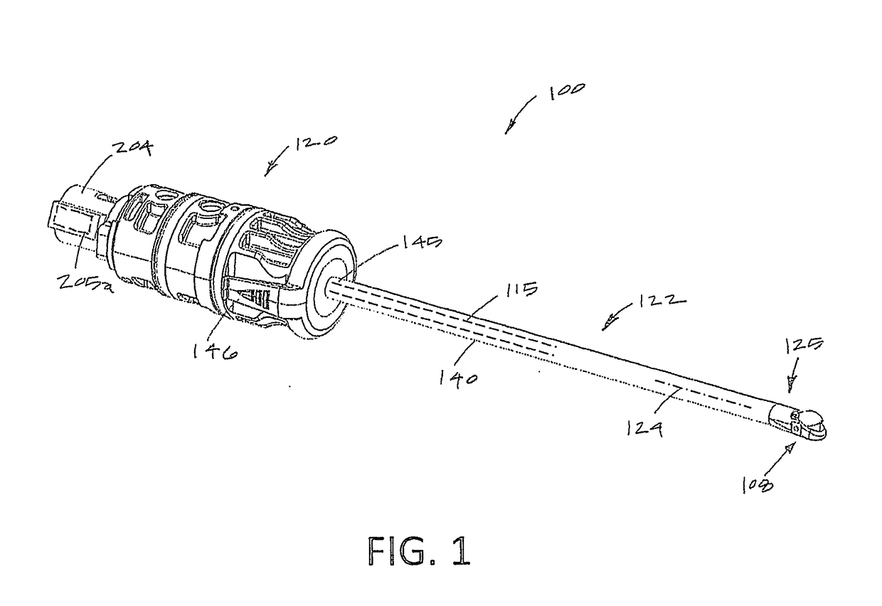
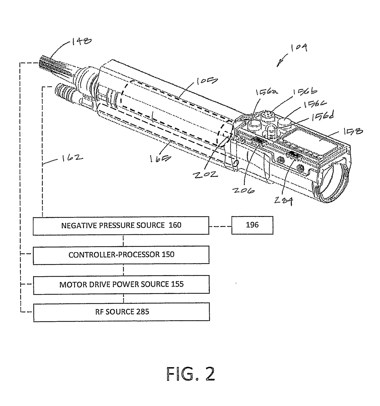
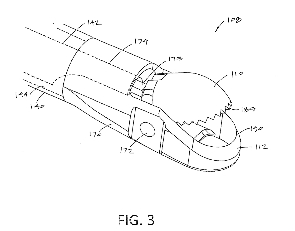
[0046]FIGS. 1-5B illustrates a tissue cutting probe 100 with a jaw structure 108 that is motor driven to close and open the jaws in a single actuation that applies high cutting forces, or alternatively, the motor drive can be actuated to close and open the jaws sequentially at 1 CPS to 100 CPS (cycle per second) to progressively nibble or cut tissue. The probe can be used in a...


PUM


Abstract

An arthroscopic device is used with a hand piece having a motor drive with a rotating drive shaft. An elongate probe extending along a longitudinal axis and includes a proximal hub on a proximal end. The proximal hub detachably couples to the hand piece, and an openable-closeable jaw structure is disposed on a distal end of the elongate probe. A conversion mechanism carried by the hub converts a rotational motion of the motor drive shaft to a longitudinal motion of an actuator member. The actuator member drives the jaw structure between jaw-open and jaw-closed positions to resect bone and other hard tissues.

Description

CROSS-REFERENCE TO RELATED APPLICATIONS[0001]This application claims the benefit of provisional application No. 62 / 563,234 (Attorney Docket No. 41879-721.103), filed on Sep. 26, 2017, the full disclosure of which is incorporated herein by reference.[0002]This application is also a continuation-in-part of application Ser. No. 15 / 483,940 (Attorney Docket No. 41879-721.201), filed on Apr. 10, 2017, which claimed the benefit of provisional application Nos. 62 / 321,114 (Attorney Docket No. 41879-721.101), filed on Apr. 11, 2017, and 62 / 325,326 (Attorney Docket No. 41879-721.102), filed on Apr. 20, 2017, the full disclosures of which are incorporated herein by reference.BACKGROUND OF THE INVENTION1. Field of the Invention[0003]This invention relates to arthroscopic tissue cutting and removal devices by which anatomical tissues may be cut and removed from a joint or other site. More specifically, this invention relates to instruments with a motor driven openable-closeable jaw that cuts tiss...

Claims


Application Information

Patent Timeline
Patent Type & Authority Applications(United States)
IPC IPC(8): A61B17/32A61B17/16
CPCA61B17/320016A61B17/1608A61B2018/00565A61B2017/00398A61B2018/00601A61B2017/00137A61B17/32002A61B2017/320028A61B2017/0046A61B18/1445A61B2018/1457A61B17/1624A61B17/1626A61B17/1628A61B2217/005
Inventor NORTON, JEFFREYNESSIM, EVANGERMAIN, AARON
Owner RELIGN CORP
Why Eureka
Try Eureka