Calender, production line for foamed floor, and once-forming process for producing foamed floor

a production line and foamed floor technology, applied in the field of mechanical manufacturing, can solve the problems of troublesome and laborious methods, low efficiency, and difficult to guarantee the embossing effect, and achieve the effects of saving materials, improving environmental performance, and improving embossing

Inactive Publication Date: 2019-01-17
QINGDAO SANYI PLASTIC MACHINERY
View PDF6 Cites 6 Cited by
  • Summary
  • Abstract
  • Description
  • Claims
  • Application Information

AI Technical Summary

Benefits of technology

[0037](1) Since the set of primary calendering rollers and the set of embossing rollers of the calender are arranged separately, the material may be cooled naturally when moving between the set of primary calendering rollers and the set of embossing rollers. Cooling rollers may also be designed for auxiliary cooling. During a cooling process, a performance of the material will be changed, so that it is advantageous to ensure a quality of subsequent processing. For example, during a processing process for a foamed floor, a material is discharged from the set of primary calendering rollers and then enters the set of embossing rollers after traveling a certain distance. During its traveling, a temperature of the foamed floor will be decreased, and a better embossing effect may be thus realized.
[0038](2) The present application provides a once-forming process for producing a WPC foamed floor, and corresponding changes are made to controls of foaming process and films attaching process. The process specifically comprises: once-forming-regimen-cutting-slotting-detecting and packaging-palletizing-putting in storage and packing. Compared with conventional production processes, the process omitting steps such as gluing, pasting and the like, so that devices are saved, and occupation space may also be saved. Since no gluing process is needed, materials can be saved and environmental performance can be improved. Since no sanding process is needed, dust pollution can be reduced. Moreover, due to streamlined operations in the production line, a labor cost can be saved.
[0039](3) In the present application, a set of temperature control strategies for the process for producing the WPC foamed floor has been studied. By setting temperatures of the set of primary calendering rollers and the set of embossing rollers and in combination with a structural design with cooling functions in the cooling and shaping device and between the set of primary calendering rollers and the set of embossing rollers, the material is modified during travelling from high temperature to low temperature, so that the foaming effect and embossing effect of finished products may be greatly improved and a rejection rate may be decreased.

Problems solved by technology

On one hand, since the layers, such as the foamed layer, the solid layers, a color film layer, a wear-resistant layer and the like, are pasted together by glue, it is low in efficiency and is not environmentally friendly; on the other hand, various steps are performed by stages, and operations in each step need to be performed by a specially-assigned person operating a special machine, so that it is troublesome and labor-consuming.
On one hand, the method is difficult to guarantee an embossing effect, and on the other hand, the production device for SPC floor cannot be directly used in a production of the WPC foamed floor.
The production devices and processes disclosed by the above patents are not suitable for once-forming production of a WPC foamed floor.
Adopting the traditional processes may cause following problems: due to the ratio of PVC powder to calcium powder has changed, a performance of the material is changed, and thus calendering process and effects of embossing and knurling may be influenced and some problems are occurred, such as failed embossing or pattern rebounded after embossing.
There is no process that can realize once-forming production of the WPC foamed floor in the prior art.

Method used


Image

  • Calender, production line for foamed floor, and once-forming process for producing foamed floor
  • Calender, production line for foamed floor, and once-forming process for producing foamed floor
  • Calender, production line for foamed floor, and once-forming process for producing foamed floor

Examples


embodiment 1

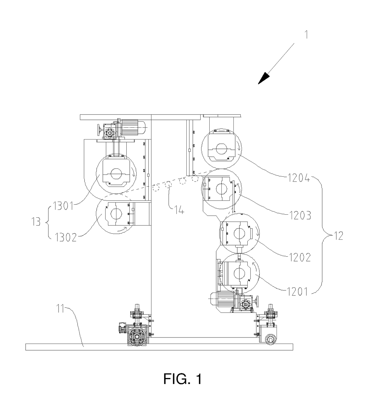
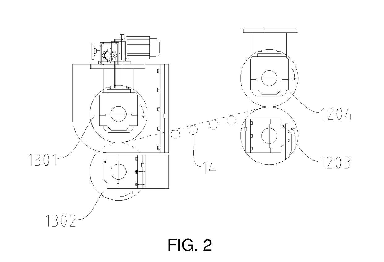
[0104]This embodiment provides a calender 1 for once-forming production of a WPC foamed floor. The calender 1 can realize a once-forming of several procedures such as foaming, embossing or knurling respectively on a bottom side and a top side of a material to be processed and so on. The embossing process means calendering a reticular pattern on a bottom of the material; and the knurling process means calendering a decorative pattern on a top surface of the material. Hereinafter, the “embossing” represents both the embossing process and the knurling process for short. In this embodiment, the material to be processed is a blank of the WPC foamed floor (hereinafter referred to as blank for short). However, in practical applications, the material to be processed is not limited to the blank of the WPC foamed floor.

[0105]The calender 1 comprises a base 11 and sets of calendering rollers arranged on the base 11. According to a material processing flow (in this embodiment, the material is t...

embodiment 2

[0116]During a production, there is another question that will result in poor quality of products and influence the embossing quality. The calender usually processes flat materials. Usually, hot extrudate is fed into the calender for processing. However, often, the hot extrudate processed by an extruder and a mold can not guarantee good flatness, and usually bent in a wavy shape.

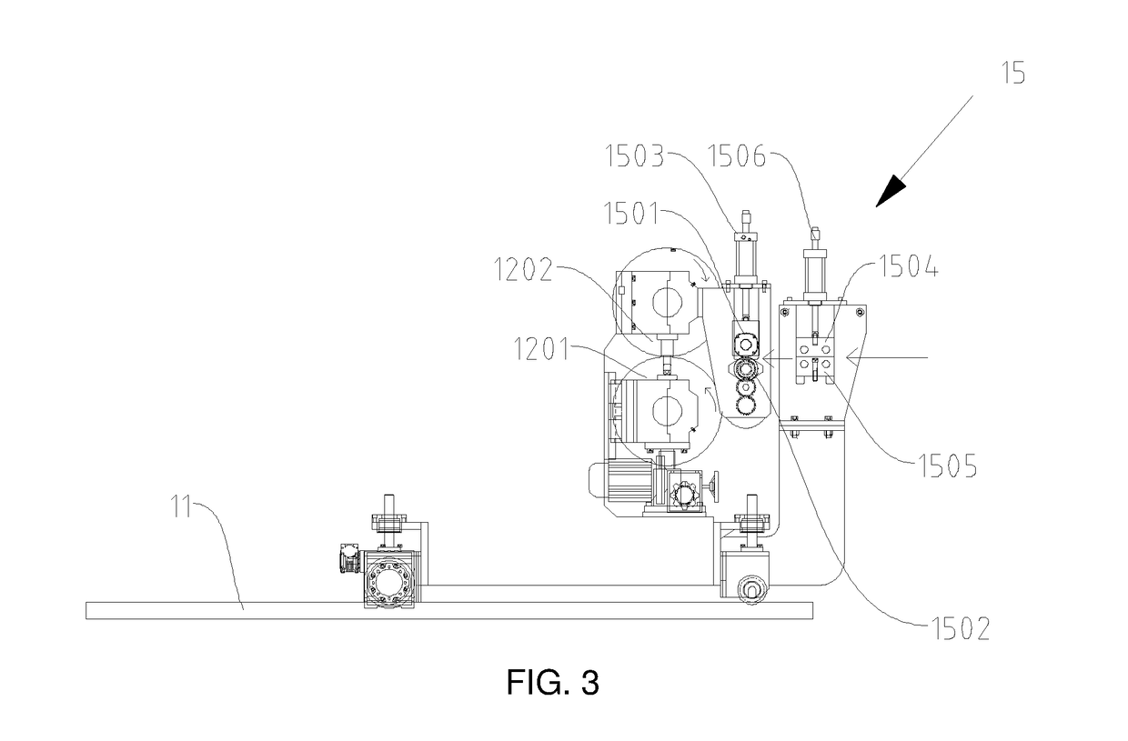
[0117]In order to ensure that the material has good flatness before entering the celender, in accordance with the processing flow of the material and based on Embodiment 1, the calender 1 further comprises a cooling and shaping device 15 which is arranged in front of the initial feed end of the set of primary calendering rollers 12 and used for cooling and shaping the material to be processed. The cooling and shaping device 15 comprises a first cooling component and a second cooling component spaced apart. A gap between the first cooling component and the second cooling component allows the material to be pr...

embodiment 3

[0126]Another structure of the calender is further provided below. The calender has a function of film attaching and calendering a material to be processed. The structure and implementation of the calender are still described by using the blank of the WPC foamed floor as the material to be processed.

[0127]Based on Embodiment 1 or 2, the calender 1 further comprises a film winding and unwinding mechanism. The film winding and unwinding mechanism comprises one or more of a substrate film winding and unwinding mechanism 161, a wear-resistant film winding and unwinding mechanism 171 and a color film winding and unwinding mechanism 181. Each of the film winding and unwinding mechanisms described above comprises two winding and unwinding wheels, one of which plays a main role while the other of which is standby during an unwinding process of the film.

[0128]As shown in FIG. 5, the film winding and unwinding mechanism in this embodiment comprises the substrate film winding and unwinding mec...


PUM

PropertyMeasurementUnit
temperatureaaaaaaaaaa

Abstract

A calender, comprising a base and a set of calendering rollers arranged on the base, wherein, the set of calendering rollers comprises a set of primary calendering rollers and a set of embossing rollers used for embossing a material to be processed; the set of primary calendering rollers and the set of embossing rollers are spaced apart for a distance to allow the material to be cooled before entering the set of embossing rollers from the set of primary calendering rollers. The calender can realize a better embossing effect, and integration production can be realized due to the use of the calender in a production of a foamed floor.

Description

CROSS-REFERENCE TO RELATED APPLICATIONS[0001]This application is a continuation-in-part of International Application No. PCT / CN2017 / 097794, filed on Aug. 17, 2017, which in turn claims the priority benefits of Chinese application No. 201710580999.5, filed on Jul. 17, 2017, Chinese application No. 201720865548.1, filed on Jul. 17, 2017, Chinese application No. 201720867916.6, filed on Jul. 17, 2017, and Chinese application No. 201720863810.9, filed on Jul. 17, 2017. The disclosure of which are hereby incorporated by reference in their entirety.TECHNICAL FIELD[0002]The present application relates to a field of mechanical manufacturing, and in particular to a calender, a production line for a foamed floor, and a once-forming process for producing a foamed floor.BACKGROUND OF THE PRESENT INVENTION[0003]Compared with a conventional wooden floor, a foamed floor has following advantages: (1) the foamed floor is soft, good at waterproofness and moisture resistance, highly elastic with good ...

Claims


Application Information

Patent Timeline
Patent Type & Authority Applications(United States)
IPC IPC(8): B29C43/24B29C43/52B29C59/04E04F15/10
CPCB29C43/24B29C43/52B29K2105/04E04F15/107B29L2031/732B29C59/04B29C43/46B29C44/5627B29C2043/461B29C2043/463B29C2043/467
Inventor ZHOU, YULIANG
Owner QINGDAO SANYI PLASTIC MACHINERY
Why Eureka
Try Eureka