
Systems and methods for high resolution imaging using a bundle of optical fibers

a high-resolution imaging and bundle technology, applied in the field of systems and methods for high-resolution imaging using a bundle of optical fibers, can solve the problems of fiber bundle based techniques suffering from limited resolution and pixilation artifacts, and the sensitivity of wavefront distortion to any bending of the fiber, so as to increase the number of speckle patterns

Inactive Publication Date: 2019-01-24
UNIV DE PROVENCE D AIX MARSEILLE I +3
View PDF4 Cites 5 Cited by
  • Summary
  • Abstract
  • Description
  • Claims
  • Application Information

AI Technical Summary

Benefits of technology

The invention describes a system and method for high resolution imaging using a fiber bundle. The system includes a lens at the end of the fiber bundle to make it easier to capture images with a high signal to noise ratio. The method involves randomly moving the fiber bundle to increase the number of speckle patterns, which are tiny interference patterns that can interfere with image quality. The method also involves randomly changing the light's wavelength, polarization state, and other factors to increase the number of speckle patterns. Overall, the invention improves the quality and accuracy of high resolution imaging.

Problems solved by technology

However, the main hurdle in applying wavefront-shaping based correction in practical endoscopic scenarios is the sensitivity of the wavefront distortion to any bending of the fiber, requiring either access to the distal end for recalibration of the wavefront correction, or precise knowledge of the bent shape for computational wavefront compensation.
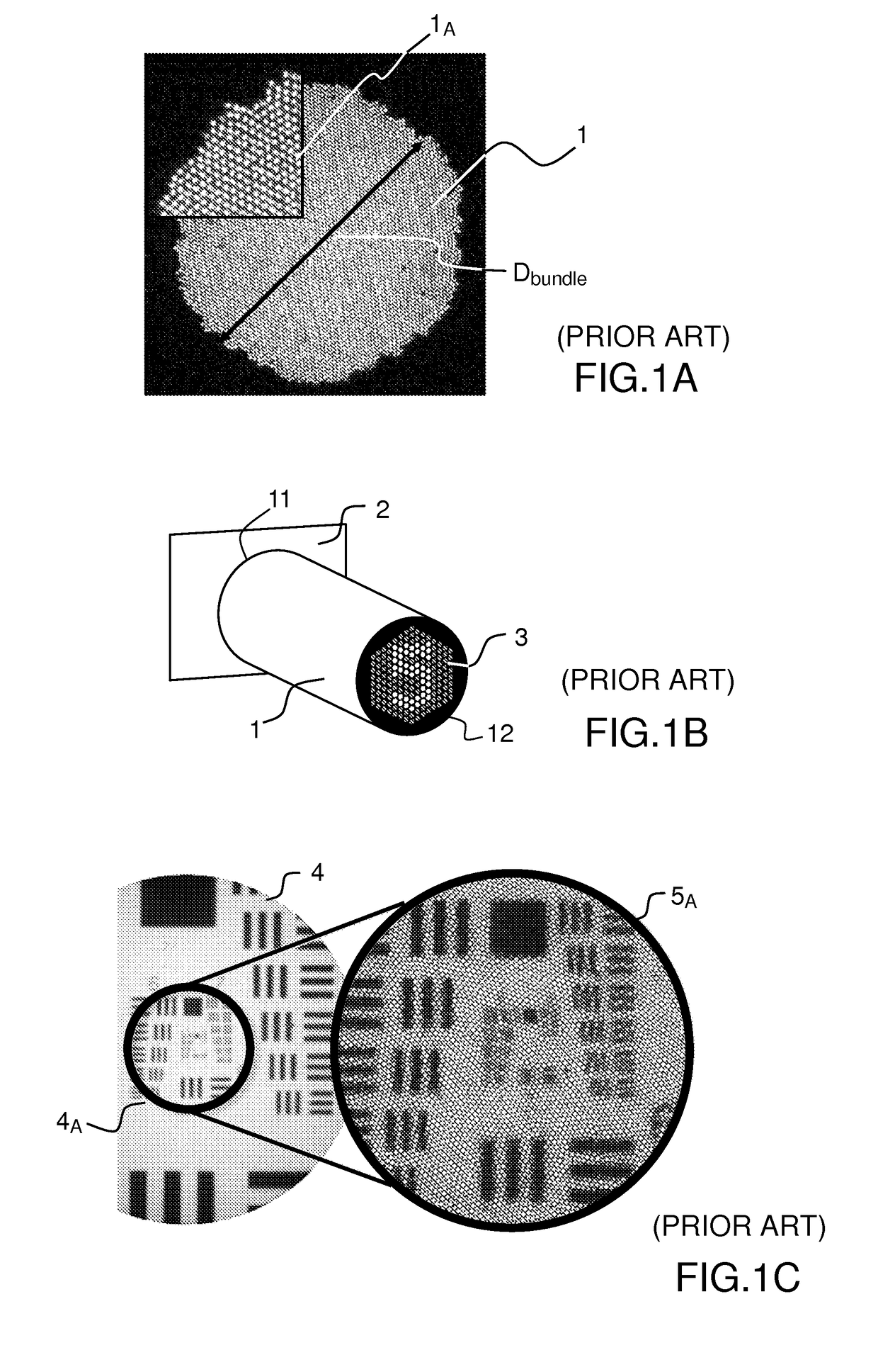
While straightforward to implement, such fiber bundle based techniques suffer from limited resolution and pixilation artifacts dictated by the individual cores and cladding diameters, and from fixed working distance which, without the addition of micro fabricated lenses, locates the target object directly at the bundle's surface.
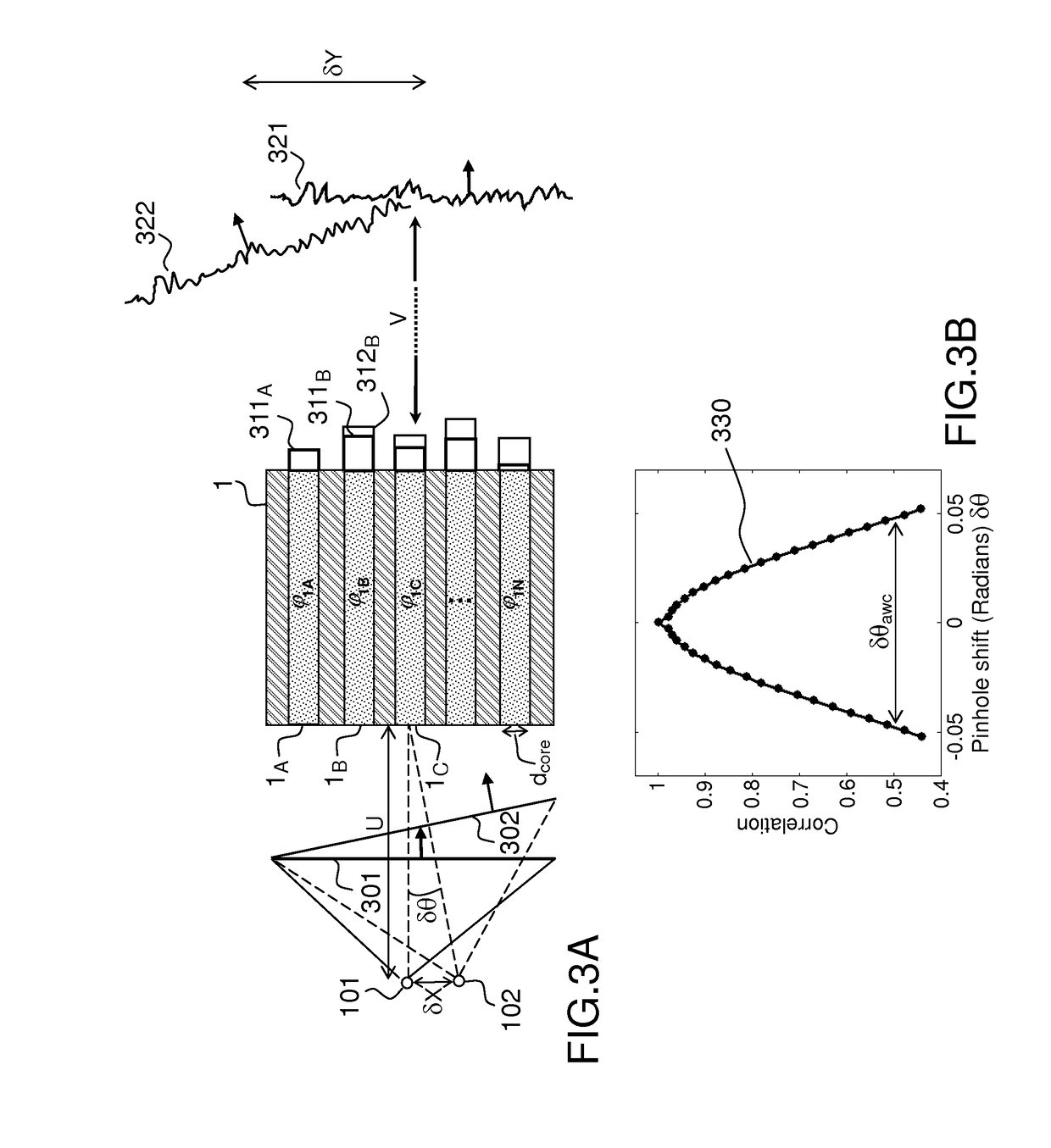
The inherent variations in refractive indices and geometries between the cores in a fiber bundle result in unpredictable fiber to fiber phase delay of the light passing through them.

Method used


Image

  • Systems and methods for high resolution imaging using a bundle of optical fibers
  • Systems and methods for high resolution imaging using a bundle of optical fibers
  • Systems and methods for high resolution imaging using a bundle of optical fibers

Examples


Embodiment Construction

[0058]In the figures, identical elements are indicated by the same references.

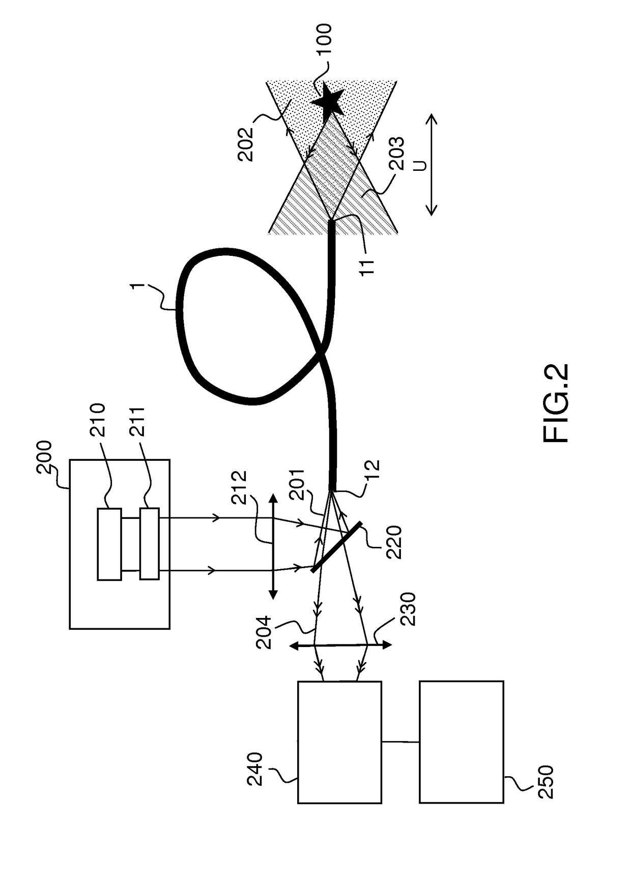
[0059]FIG. 2 shows an example of a system for high resolution imaging of an object, according to a first embodiment of the description.

[0060]The system as shown in FIG. 2 may be applied to endoscopic imaging or any remote imaging where a fiber bundle is advantageously used between the object and the detector.

[0061]The system for high resolution imaging comprises a fiber bundle 1 of length L. The fiber bundle may be a fiber bundle as shown in FIG. 1A, and comprises an array of optical fiber cores 1A. The system for high resolution imaging further comprises, at a proximal end of the fiber bundle, a two-dimensional detector 240 and a processing unit 250. The two-dimensional detector 240 is placed a non-zero distance from the fiber bundle's proximal facet.

[0062]The system for high resolution imaging may further comprise a source 200 for illuminating the object 100 in applications where objects are not self emi...


PUM


Abstract

According to one aspect, the present description relates to a system for high resolution imaging of an object comprising a fiber bundle (1) comprising an array of optical fiber cores (A), said fiber bundle being adapted to receive a plurality of light beams issued from spatially incoherent point sources of an object; the system further comprises a two-dimensional detector (240) with a detection plane, located at a proximal end of the fiber bundle, adapted to receive speckle patterns, each speckle pattern resulting from the transmission of one of said light beams through at least a plurality of the fiber bundle cores, the ensemble of speckle patterns detected by the two-dimensional detector forming a multiple speckles image; and a processing unit (250) adapted to determine an image of the object from said multiple speckles image.

Description

PRIOR ARTTechnical Field[0001]The present description relates to systems and methods for high resolution imaging using a bundle of optical fibers. It is applicable but not limited to endoscopic imaging.Prior Art[0002]Flexible optical endoscopes are one of the most important tools in biomedical investigation and clinical diagnostics. They enable imaging deep inside complex samples, at depths where scattering prevents conventional noninvasive microscopic investigation. An ideal micro endoscopic probe should allow real time, diffraction-limited imaging at various axial distances from its facet (distal end), together with the smallest possible cross-sectional footprint to minimize tissue damage.[0003]Recently, there has been a surge of works employing wavefront-shaping for lens less micro endoscopy through single multimode fibers. In the published Patent Application US 2015 / 0015879 for example, a multimode waveguide illuminator and imager is shown, relying on a wave-front shaping system...

Claims


Application Information

Patent Timeline
IPC IPC(8): H04N5/232G02B6/06G02B27/14G02B27/48
CPCH04N5/23232G02B6/06G02B27/141G02B27/48H04N2005/2255H01S3/005H04N23/951H04N23/555
Inventor RIGNEAULT, HERVEANDRESEN, ESBENPORAT, AMIRORON, DANKATZ, ORIGIGAN, SYLVAIN
Owner UNIV DE PROVENCE D AIX MARSEILLE I
Learn More