Fully Automatic Microscopic Scanner

a fully automatic, scanner technology, applied in the field of microscopic image scanning, can solve the problems of low scanning efficiency, low scanning efficiency, and the mechanism does not fundamentally solve the problem, and achieve the effect of saving cost and quick scanning

Active Publication Date: 2019-01-31
LI XINYU
View PDF0 Cites 14 Cited by
  • Summary
  • Abstract
  • Description
  • Claims
  • Application Information

AI Technical Summary

Benefits of technology

[0061]10. The present invention also provides a more favorable condition for scanning a larger area of the pathological slides by setting a scanning mode in which the micro scanning unit and the line array camera are linked with the light source mechanism. The technical purpose of saving cost and quick scanning can also be achieved by setting two groups of microscopic scanning units and a linear array camera to link a linear light source corresponding to the scan modes of two rows of items to be detected.

Problems solved by technology

However, this system may scan only one slide at a time because it cannot get out of the traditional microscope structure.
Therefore, scanning efficiency is low.
In order to solve this problem, many manufacturers have researched and developed a variety of automatic slide-feeding mechanisms to fulfil the need for unattended large-scale scanning beyond 8-hours-service times that are not possible in manual slide-feeding modes.
But this automatic mechanism does not fundamentally solve the problem of low scanning efficiency.
On the other hand, due to the lack of an industry standard thickness of pathological slides, the automatic slide-feeding mechanism is prone to failure.
This leads to unattended scanning equipment failure which seriously impacts the next working day.
Additionally, traditional methods fail to scan a large number of previously stored pathological slides efficiently.
This seriously restricts scanning speed.
More importantly, if the object being scanned (e.g. an object in 96-well plate) is a liquid, the motion of a typical micro-scanning equipment base causes the liquid to shake.
Thus, a quick scan cannot be conducted to get a clear image via a mobile scanning process.
It is evident that the methods and the use of the above-mentioned existing micro-scanning equipment are inconvenient and have too many defects.
While existing units may be suitable for the particular purpose employed, or for general use, they would not be as suitable for the purposes of the present disclosure as disclosed hereafter.

Method used


Image

  • Fully Automatic Microscopic Scanner
  • Fully Automatic Microscopic Scanner
  • Fully Automatic Microscopic Scanner

Examples


embodiment 1

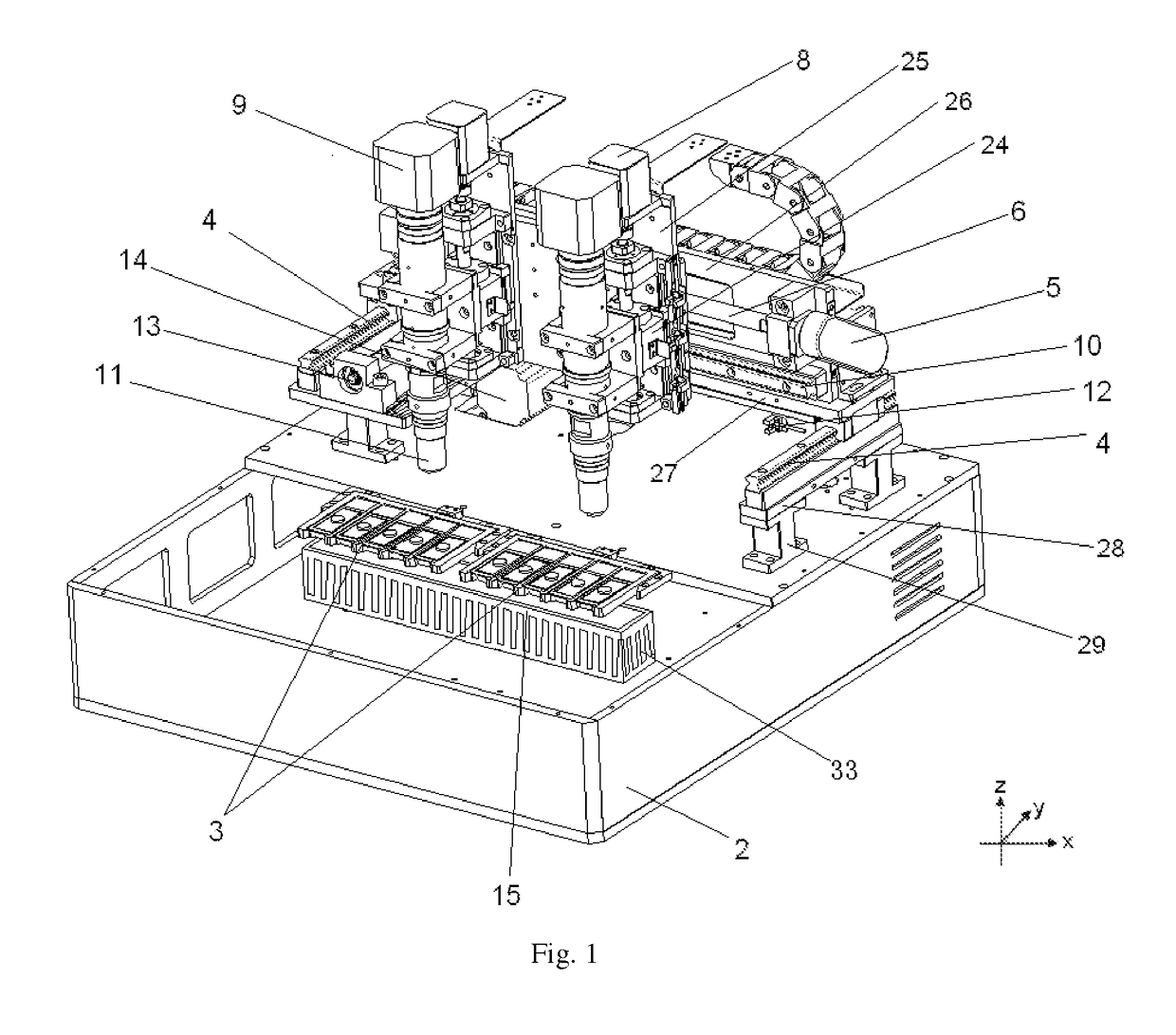
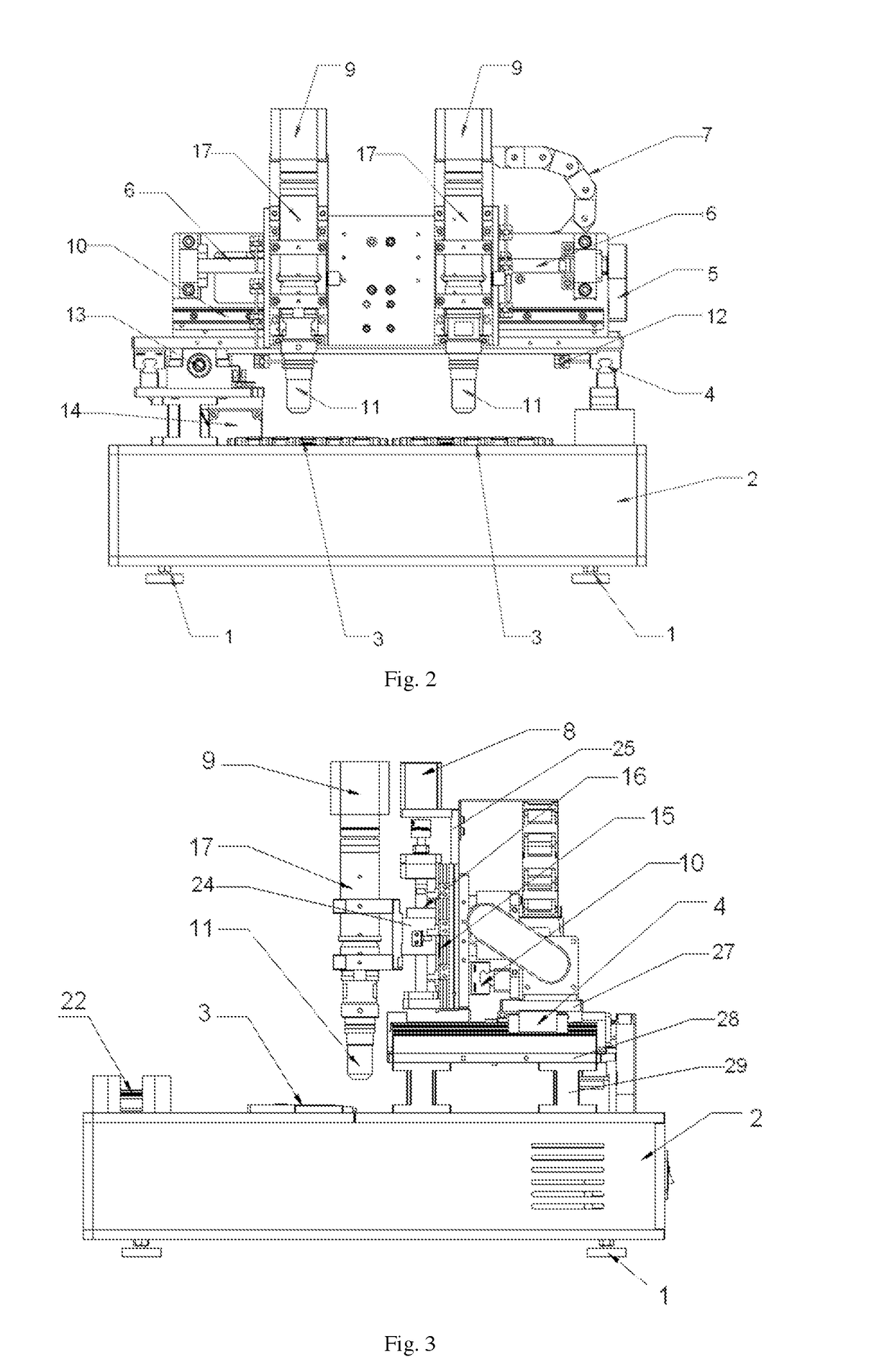
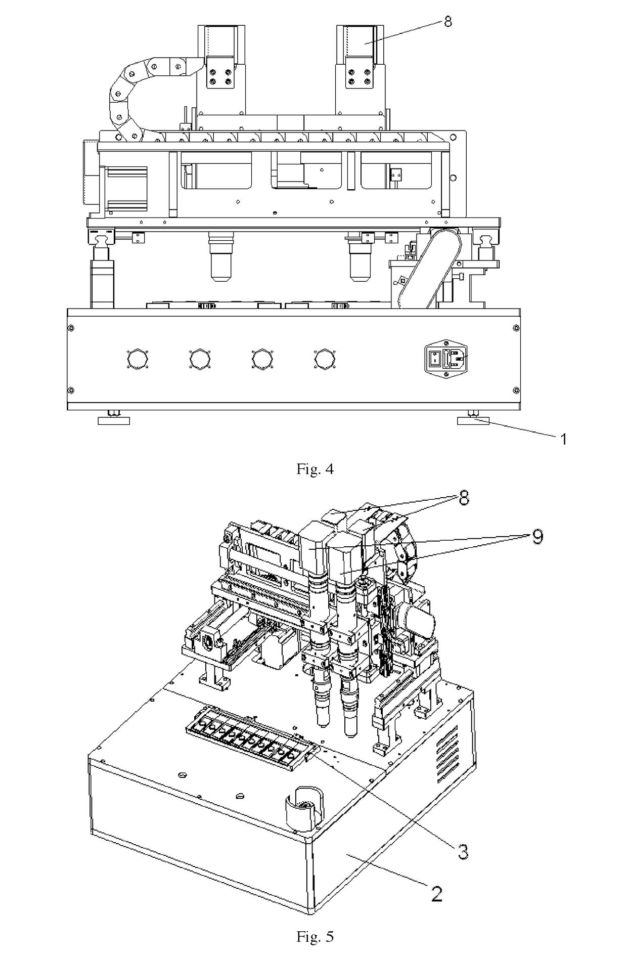
[0076]As shown in FIGS. 1-4, the fully automatic microscopic scanner in this embodiment comprises an image acquisition mechanism (IAM) 9, a microscopic scanning mechanism, a stage mechanism 3 and a light source mechanism 15. The IAM 9 adopts a line array camera to enable rapid scanning of pathological slides.

[0077]The microscopic scanning mechanism comprises a lens tube 17 capable of adjusting magnification and a replaceable lens 11. The IAM 9 is connected to the lens tube 17, with the replaceable lens 11 being above the stage mechanism 3, and the light source mechanism 15 being right below the stage mechanism 3.

[0078]In this embodiment, the stage mechanism 3 and the light source mechanism 15 are fixed, and the microscopic scanning mechanism and the IAM 9 can, under the action of a power control mechanism, move along X-axis, Y-axis, and Z-axis, that is, the replaceable lens 11 can move leftwards and rightwards, forwards and backwards, up and down, relative to the stage mechanism 3, ...

embodiment 2

[0104]As shown in FIGS. 10 and 11, the difference between the present embodiment and the first embodiment is that the light source mechanism 15′ of the fully automatic microscopic scanner is connected with a power control mechanism and controlled by the power control mechanism which achieves the linkage of the microscopic scanning mechanism and the IAM in the X-axis and Y-axis directions.

[0105]Specifically, in the present embodiment, the light source mechanism 15′ is connected to the Z-axis fixing plate through the connecting plate and when the X-axis ball screw is driven by the X-axis motor to drive the Z-axis fixing plate to move left and right, the Z axis fixing plate will drive the light source mechanism 15′ and the Z-axis movement control unit, the microscopic scanning mechanism and the IAM to perform a left-right movement relative to the stage mechanism 3. In addition, when the Y-axis ball screw is driven by the Y-axis motor and the Y-axis fixing plate is moved back and forth,...


PUM


Abstract

A fully automatic microscopic scanner, comprising an image acquisition mechanism (IAM) with a line array camera. The IAM and the microscopic scanning mechanism can move along X/Y/Z axis under the action of a power control mechanism and the stage mechanism and the light source mechanism are fixed and not moved. The light source mechanism comprises a flat light source with a condenser and the flat light source area is greater than or equal to the total area of the tray. The light source mechanism comprises a cooling fan and a water cooling unit. It also comprises a general control mechanism and a laser pre-focus system connected to it. The invention also discloses a fully automatic microscopic scanner which links the microscopic scanning mechanism and the IAM with the light source mechanism. According to the present invention, flexible adjustment of lens can be achieved to make the lens move forwards and backwards, leftwards and rightwards and up and down. In addition, with the unique light source mechanism and laser pre-focus system, the stage and the light source are fixed and not moved during the scanning process so that real-time accurate and fast focusing might be fulfilled. In such a way, unlimitedly extended microscopic scanning range, improved scanning efficiency and improved quality of scanning can be accomplished.

Description

CROSS-REFERENCE TO RELATED APPLICATIONS[0001]This application is a bypass continuation-in-part of and claims priority under 35 U.S.C. §§ 111(a), 363 to a Patent Cooperation Treaty application PCT / CN2017 / 095135 filed in the People's Republic of China Patent Office on Jul. 31, 2017, which claims priority to of the patent applications, serial numbers 2017206557713 and 2017104242588, filed in the People's Republic of China on Jun. 7, 2017 and claims the priority thereof and is expressly incorporated herein by reference in its entirety.[0002]This application is related to a Patent Cooperation Treaty application PCT / CN2018 / 090292, filed in the People's Republic of China Patent Office on Jun. 7, 2018 and which is a continuation-in-part of and claims the priority thereof to the same applications listed hereinabove.TECHNICAL FIELD[0003]The present disclosure relates generally to microscopic image scanning. More particularly, the present disclosure relates to a fully automatic image scanner.B...

Claims


Application Information

Patent Timeline
Patent Type & Authority Applications(United States)
IPC IPC(8): G02B21/00G02B21/26G02B21/24G02B7/02
CPCG02B21/0036G02B21/0032G02B21/26G02B21/245H04N5/2253H04N5/247G02B7/023G02B21/06G02B21/24G02B21/361G02B21/002G02B21/086H04N23/60H04N23/54H04N23/90
Inventor LI, XINYU
Owner LI XINYU
Why Eureka
Try Eureka