
Prosthetic Heart Valve

a heart valve and prosthesis technology, applied in the field of prosthetic heart valves, can solve the problems of increasing total stroke volume and reducing cardiac output, and achieve the effect of facilitating one-way blood flow

Active Publication Date: 2019-02-07
CARDIOVALVE LTD
View PDF2 Cites 39 Cited by
  • Summary
  • Abstract
  • Description
  • Claims
  • Application Information

AI Technical Summary

Benefits of technology

The patent text describes a prosthetic valve that can be delivered to the heart through a blood vessel and expanded once there to allow blood to flow through it in one direction. This invention allows for a minimally invasive heart valve replacement.

Problems solved by technology

Regurgitation of blood from the ventricle into the atrium results in increased total stroke volume and decreased cardiac output, and ultimate weakening of the ventricle secondary to a volume overload and a pressure overload of the atrium.

Method used


Image

  • Prosthetic Heart Valve
  • Prosthetic Heart Valve
  • Prosthetic Heart Valve

Examples


Embodiment Construction

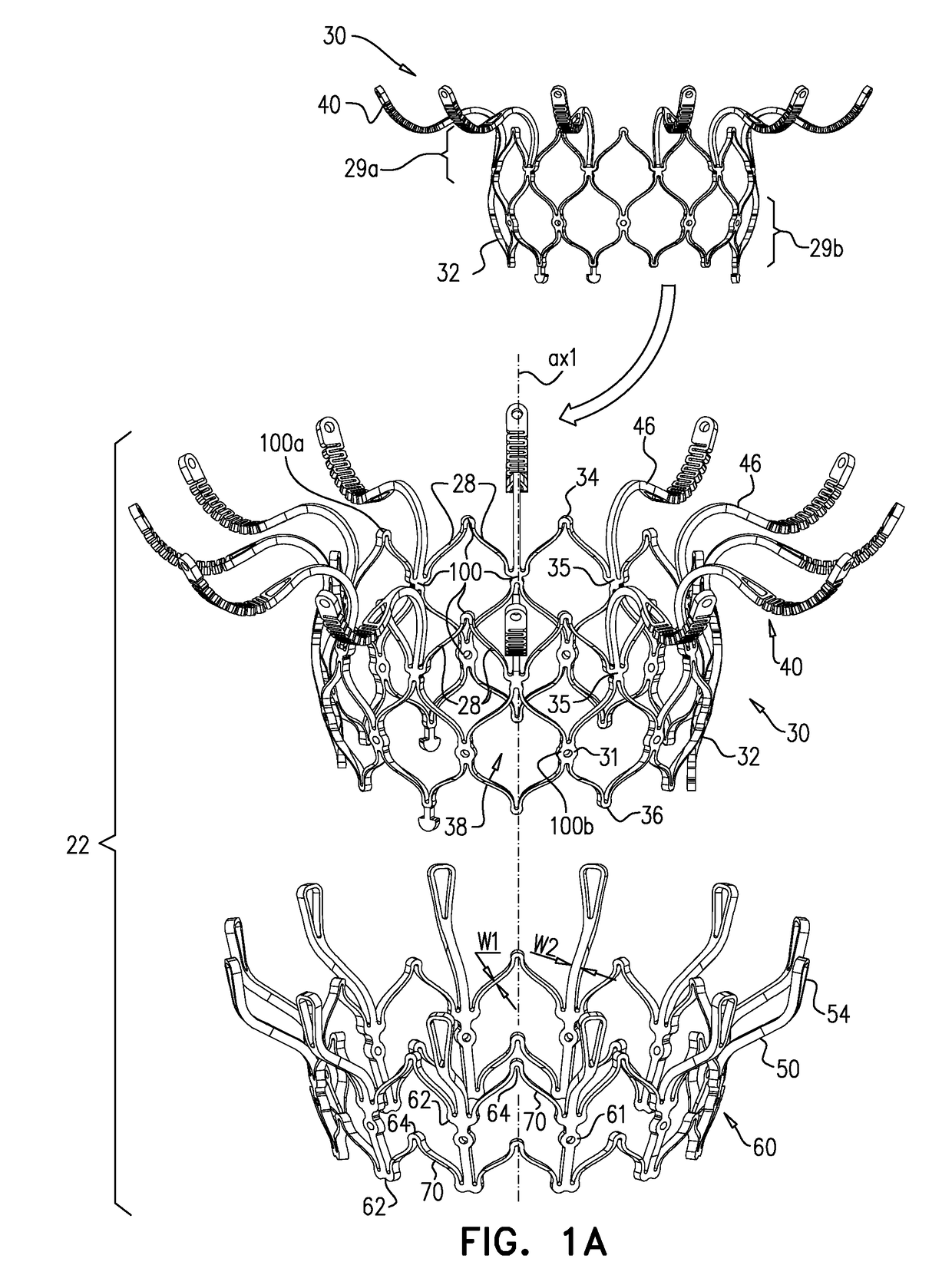
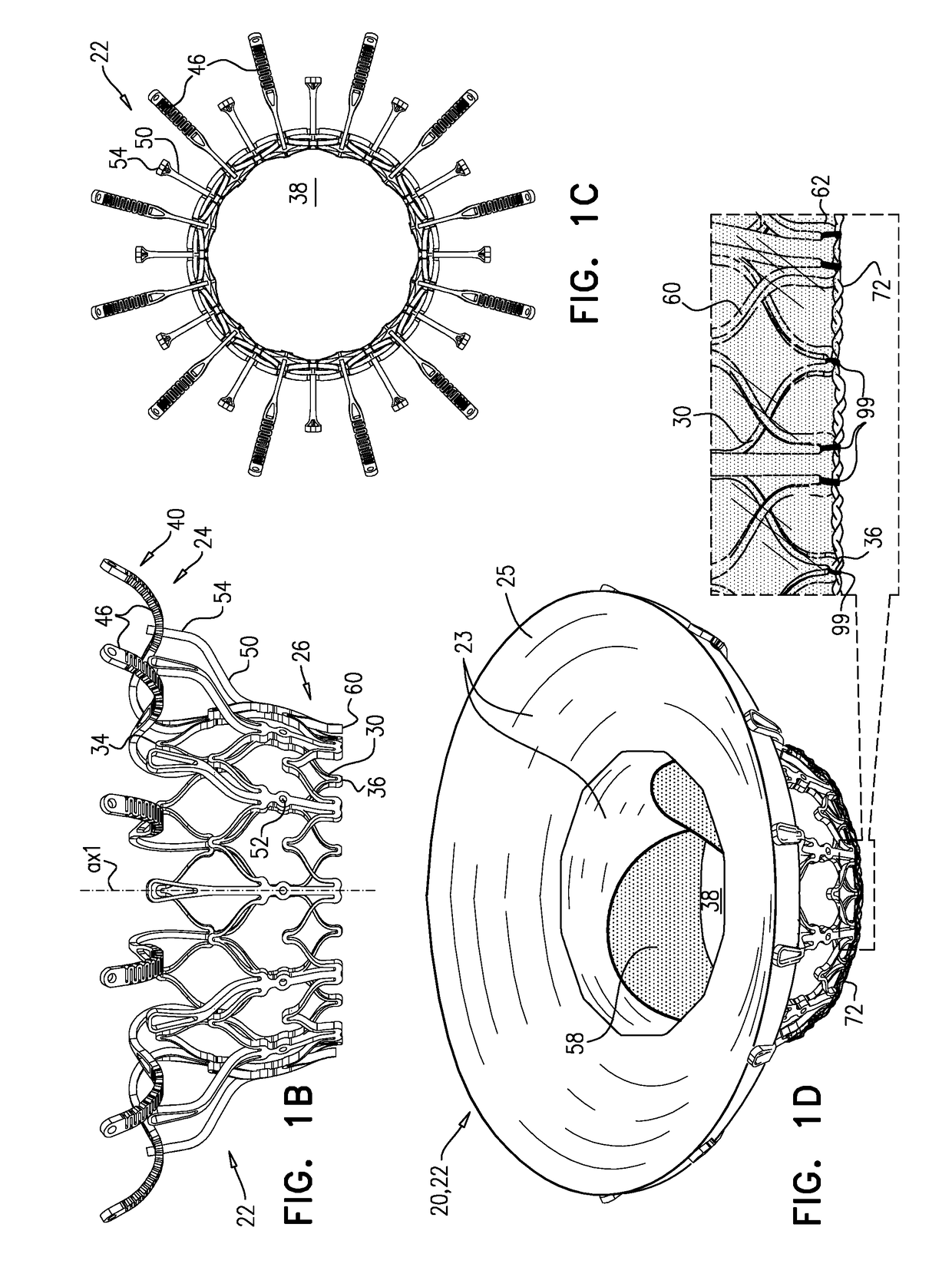
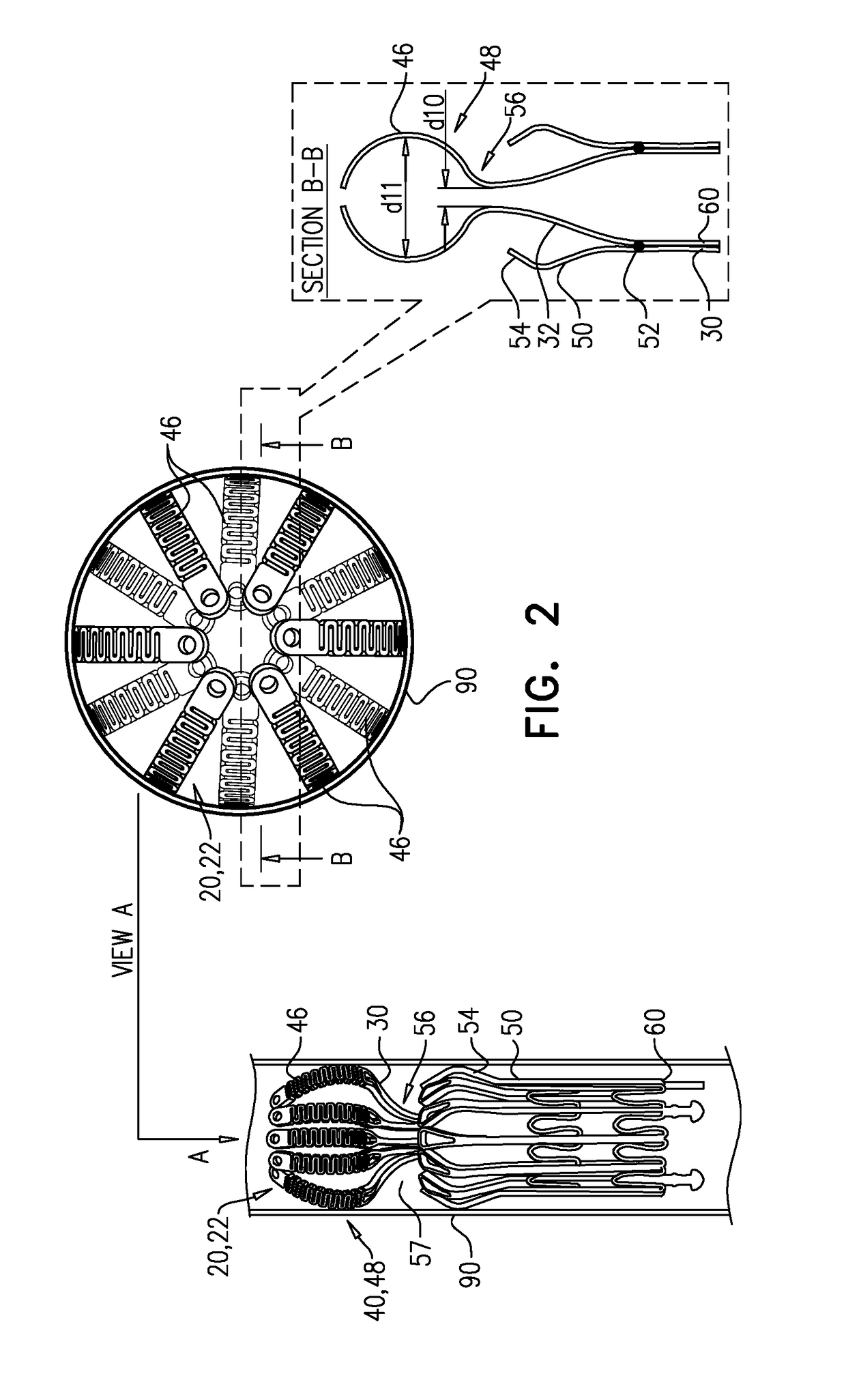
[0143]Reference is made to FIGS. 1A-D and 2, which are schematic illustrations of an implant 20 and a frame assembly 22 of the implant, in accordance with some applications of the invention. Implant 20 serves as a prosthetic valve for use at a native heart valve of a subject—typically the mitral valve. Implant 20 has a compressed state for minimally-invasive (typically transluminal, e.g., transfemoral) delivery, and an expanded state into which the implant is transitioned at the native heart valve, and in which the implant provides prosthetic valve functionality. Implant 20 comprises frame assembly 22, a covering 23, and a valve member, such as prosthetic leaflets 58.

[0144]FIGS. 1A-D show implant 20 and frame assembly 22 in the expanded state. For clarity, FIGS. 1A-C show frame assembly 22 alone. FIG. 1A shows an exploded view of frame assembly 22, and FIGS. 16 and 1C are side- and top-views, respectively, of the frame assembly assembled. FIG. 1D is a perspective view of implant 20,...


PUM


Abstract

A tubular valve body has an upstream end and a downstream end, and has a central longitudinal axis, and defines a lumen along the axis. Prosthetic leaflets are disposed within the lumen, and are configured to facilitate one-way movement of fluid through the lumen in an upstream-to-downstream direction. The valve body has a cellular structure defined by a plurality of joists connected at nodes, the joists and nodes delimiting cells of the cellular structure. The nodes include minor nodes at which 2-4 joists are connected, and major nodes at which 6-8 joists are connected. The cells of the cellular structure comprise a first circumferential row of first-row cells. Each of the first-row cells is connected to each of its circumferentially-adjacent first-row cells at a respective one of the major nodes, and is longitudinally delimited by two of the minor nodes. Other embodiments are described.

Description

FIELD OF THE INVENTION[0001]Some applications of the present invention relate in general to valve replacement. More specifically, some applications of the present invention relate to prosthetic valves for replacement of a cardiac valve.BACKGROUND[0002]Ischemic heart disease causes regurgitation of a heart valve by the combination of ischemic dysfunction of the papillary muscles, and the dilatation of the ventricle that is present in ischemic heart disease, with the subsequent displacement of the papillary muscles and the dilatation of the valve annulus.[0003]Dilation of the annulus of the valve prevents the valve leaflets from fully coapting when the valve is closed. Regurgitation of blood from the ventricle into the atrium results in increased total stroke volume and decreased cardiac output, and ultimate weakening of the ventricle secondary to a volume overload and a pressure overload of the atrium.SUMMARY OF THE INVENTION[0004]For some applications, an implant is provided having ...

Claims


Application Information

Patent Timeline
IPC IPC(8): A61F2/24A61F2/86
CPCA61F2/2418A61F2230/0063A61F2/01A61F2/86A61F2/2412A61F2/2436A61F2240/001A61F2240/004
Inventor IAMBERGER, MENIBAUM, AVIRAMHARARI, BOAZHARITON, ILIA
Owner CARDIOVALVE LTD
Features
  • Generate Ideas
  • Intellectual Property
  • Life Sciences
  • Materials
  • Tech Scout
  • Unparalleled Data Quality
  • Higher Quality Content
  • 60% Fewer Hallucinations
Learn More