Connecting gusset plate with sliding end plate for buckling-restrained brace

a technology of buckling-restrained braces and sliding end plates, which is applied in the direction of building types, construction, building repairs, etc., can solve the problems of buckling-restrained braces that cannot be welded, the failure mode of beam-columns to be transferred, and the effect of reducing the effective length of beam-columns

Active Publication Date: 2019-02-07
SOUTH CHINA UNIV OF TECH +1
View PDF0 Cites 4 Cited by
  • Summary
  • Abstract
  • Description
  • Claims
  • Application Information

AI Technical Summary

Benefits of technology

[0006]2. Transfer of Failure Mode of the Beam-Column and Change in the Effective Length Thereof
[0007]The results of tests for the buckling-restrained braced frames existing in China and abroad show that the rigid zone effect may cause the transfer of yielding (failure) section of the beam-column from the end of the beam to the end of the gusset plate, and cause a peak value of plastic deformation thereof to be 32 times of that of a model without a rigid zone. In addition, the rigid zone effect may decrease an effective length of the beam-column, cause the failure mode of the beam-column to be transferred from bending failure to shear failure, and aggravate the tendency of brittle failure in the reinforced concrete beam-column member, which will be fatal in a large earthquake.
[0008]3. Adverse Impact of the Opening-Closing Effect of the Beam-Column on the Gusset Plate
[0009]The studies show that the beam and column will experience significant bending deformation (the flanges thereof are subjected to elongating or compressive deformation) under the seismic shear force. But the rigid zone effect of the gusset plate restrains the beam and column from deforming freely. An additional acting force (termed Opening-Closing effect) is thus generated at the connection welds between the gusset plate and the flanges of the beam and column, causing premature fracture of the connection weld of the gusset plate, and even leading to out-of-p...

Problems solved by technology

The buckling-restrained brace provides lateral stiffness to the structure during a small earthquake, and tends to dissipate earthquake energy during a moderate or large earthquake.
The currently existing tests and finite element analysis results show that such rigid zone effect may significantly increase the lateral stiffness of the main structure and result in an increase of the seismic shear force sustained by the structure, thereby causing premature failure of the structure (see the second point for details), which in turn weakens the advantageous effects that the buckling-restrained braced structure should possess.
However, during the design of structures, engineers often neglect the impacts of this rigid zone effect due to the problems such as complication of computer modeling, which will result in a large deviation between the actual performance and the designed performance of the buckling-restrained braced structure system, leading to potential man-made risk to the safety of such structures when subjected to a large earthquake.
The results of tests for the buckling-restrained braced frames existing in China and abroad show that the rigid zone effect may cause the transfer of yielding (failure) section of the beam-column from the end of the beam to the end of the gusset plate, and cause a peak value of plastic deformation thereof to be 32 times of that of a model without a rigid zone.
In addition, the rigid zone effect may decrease an effective length of the beam-column, cause the...

Method used


Image

  • Connecting gusset plate with sliding end plate for buckling-restrained brace
  • Connecting gusset plate with sliding end plate for buckling-restrained brace
  • Connecting gusset plate with sliding end plate for buckling-restrained brace

Examples


first embodiment

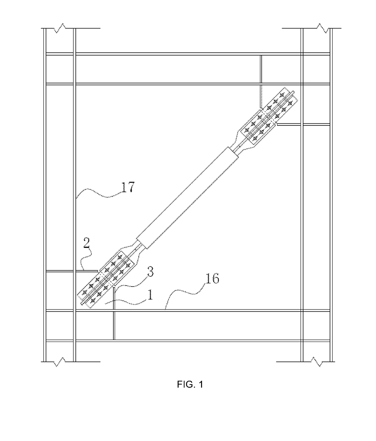
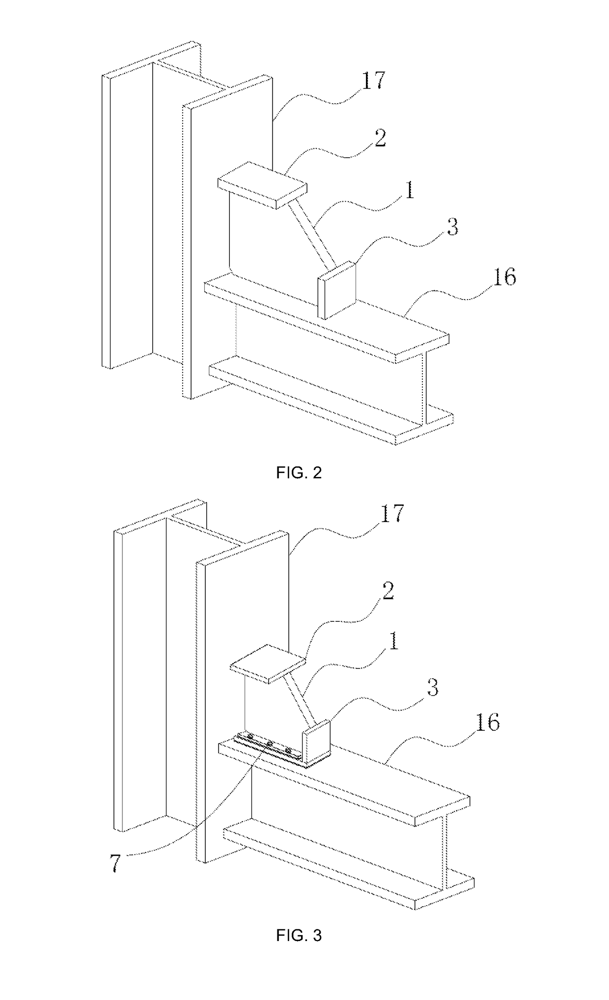
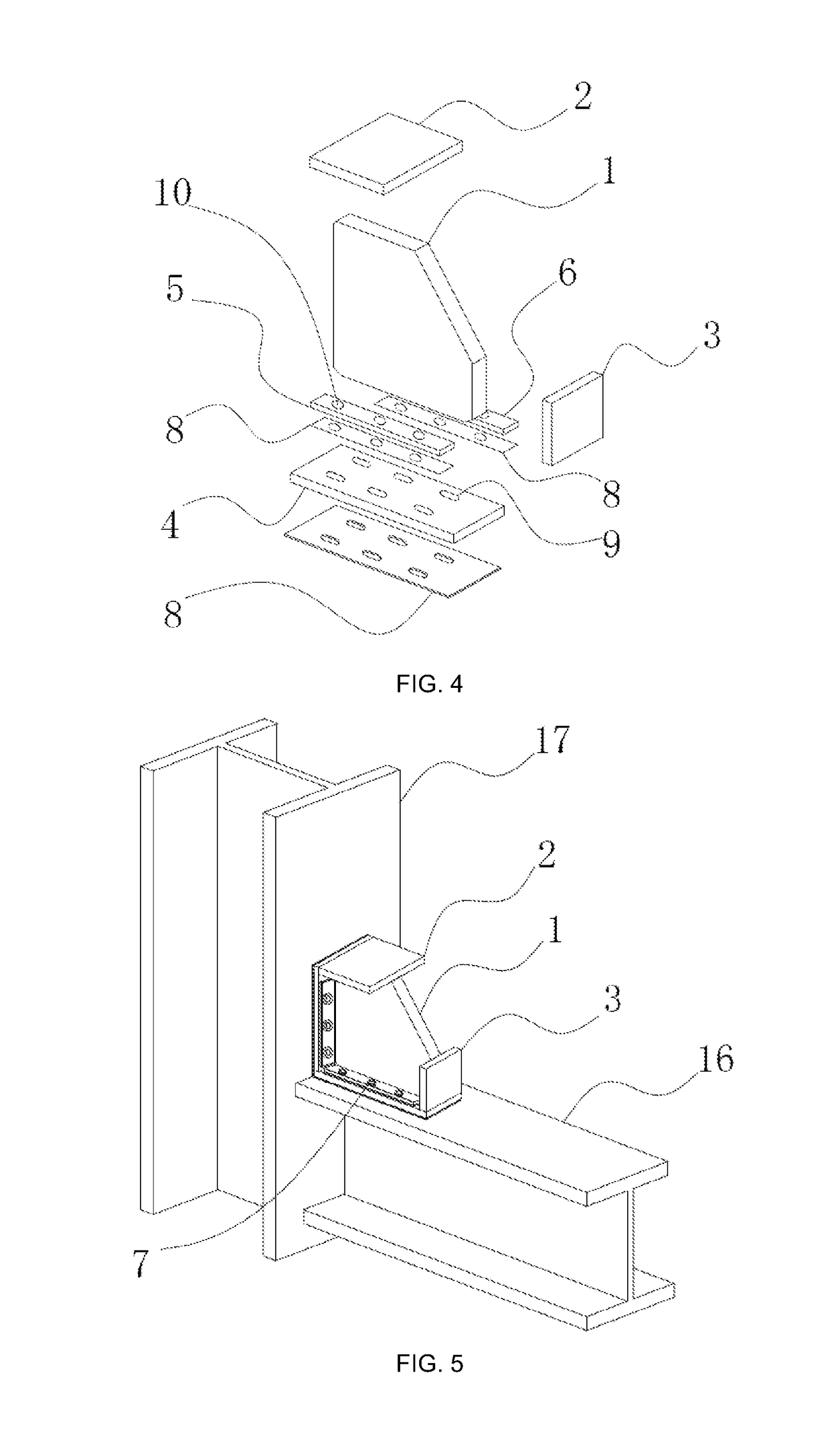
[0034]The present embodiment provides a gusset plate connection with sliding end plates for a buckling-restrained brace, where FIG. 1 is a structural diagram showing the overall connection between a buckling-restrained brace and beam column, FIG. 3 is a structurally schematic diagram of a gusset plate connection with sliding end plates for a buckling-restrained brace provided in the first embodiment of the present disclosure, and FIG. 4 is an exploded view of the gusset plate connection with sliding end plates for a buckling-restrained brace provided in the first embodiment of the present disclosure. As shown in FIGS. 1, 3 and 4, the main structure of the gusset plate connection with sliding end plate for a buckling-restrained brace comprises a central plate 1, a first rib plate 2, a second rib plate 3, a horizontal end plate 4, a first horizontal tie plate 5, a second horizontal tie plate 6, bolts 7, and unbonding layers 8. Specifically, the horizontal end plate 4 is perpendicular ...

second embodiment

[0039]In the second embodiment, the gusset plate connection with sliding end plates is further provided with a vertical end plate 11, a first vertical tie plate 12, and a second vertical tie plate 13. FIG. 5 is a schematic diagram of the structure of a gusset plate connection with sliding end plates for a buckling-restrained brace provided in the second embodiment of the present disclosure; and FIG. 6 is an exploded view of the gusset plate connection with sliding end plates for a buckling-restrained brace provided in the second embodiment of the present disclosure. Specifically, as shown in FIGS. 5 and 6, the vertical end plate 11 is perpendicular to both of the central plate 1 and the horizontal end plate 4, and is fixedly disposed with respect to the first rib plate 2 on a left end surface of the central plate 1. The first vertical tie plate 12 and the second vertical tie plate 13 are both disposed on a right surface of the vertical end plate 11, and are respectively located at e...


PUM


Abstract

Disclosed is a gusset plate connection with sliding end plates for a buckling-restrained brace, including central plate (1), first rib plate (2), second rib plate (3), horizontal end plate (4), first horizontal tie plate (5), second horizontal tie plate (6), bolts (7) and unbonding layers (8). Horizontal end plate (4) is perpendicular to the central plate (1) and fixedly disposed on a lower end surface of central plate (1). First horizontal tie plate (5) and second horizontal tie plate (6) are both disposed on an upper surface of horizontal end plate (4) and are located at two sides of central plate (1), respectively. Unbonding layers (8) are each disposed at a bottom surface of horizontal end plate (4), between horizontal end plate (4) and first horizontal tie plate (5), and between horizontal end plate (4) and second horizontal tie plate (6). The components are connected by means of bolts (7).

Description

CROSS REFERENCE TO RELATED APPLICATION[0001]The present disclosure claims priority to Chinese Patent Application No. 201610333205.0, filed on May 19, 2016, and entitled “Gusset Plate Connection with Sliding End Plates for Buckling-Restrained Brace”, which is incorporated herein by reference in its entirety.TECHNICAL FIELD[0002]The present disclosure relates to the technical field of civil architectural structures, and in particular to a gusset plate connection with sliding end plates for buckling-restrained brace.BACKGROUND ART[0003]Buckling-restrained braces are currently used, as a new type of energy dissipation-seismic reduction members, in civil architectural structures, especially in multistoried tall buildings. The buckling-restrained brace provides lateral stiffness to the structure during a small earthquake, and tends to dissipate earthquake energy during a moderate or large earthquake. In practical application, the buckling-restrained brace must be connected to beam and col...

Claims


Application Information

Patent Timeline
IPC IPC(8): E04H9/02E04B1/58E04B1/98E04B1/24
CPCE04B1/5812E04B1/98E04B1/2403E04B2001/2415E04B2001/2448E04B2001/2457E04H9/021E04H9/024E04H9/0237E04H9/027E04B2001/2496E04G23/0218
Inventor ZHAO, JUNXIANCHEN, RUOBINGYU, HAICHAOHAN, WEI
Owner SOUTH CHINA UNIV OF TECH
Why Eureka
Try Eureka